One of the most important characteristics of the current transformer is its magnetization characteristics. This is the dependence of the voltage on the outputs secondary winding from the current flowing through it. Therefore, the characterization called volt-ampere (VAC). In this case, the outputs of the primary winding remain open, and the voltage to the secondary winding is supplied from an independent source with a regulated output.
These characteristics are removed both during acceptance tests and during operation. The purpose of the test: to identify possible turn short circuits in the secondary winding of the tested transformer. The usual measurement of resistance cannot reveal this defect, since the closure of several turns between themselves changes the total resistance so slightly that it is commensurate with the measurement error.
The check is carried out for all current transformers without exception: both for voltage up to 1000 V and high-voltage ones. If the transformer has several windings used for different purposes ( relay protection, measurement, electricity metering) I–V characteristics are taken for each of them.
Equipment and scheme for testing
A laboratory autotransformer (LATR), or devices containing it in its composition, is used as an adjustable voltage source for removing the I–V characteristics. The voltage must be absolutely sinusoidal, so thyristor power supplies are not suitable for testing.
To fix the values of currents and voltages, a laboratory ammeter and voltmeter will be required. When using devices built into the power supply, it is important to consider that the ammeter should measure the rms value, and the average rectified value.
The order in which devices are included in the measuring circuit is also important. The ammeter should only measure the current directly in the winding under test. The voltmeter is connected before it, the current through the winding of the device should not be taken into account so as not to introduce an additional error into the measurements.
The most accurate measurement option is to connect the measuring complex directly to the terminals of the current transformer. But, if this is not possible, a variant is allowed using special current terminals on the panels of the cell with the current transformer being tested. Measurement from terminal blocks located at a considerable distance and connected to the object of measurement control cables, is unacceptable. In this case, the core resistance is added to the winding resistance cable line commensurate with it in size.
It is not possible to check the current transformer for voltage up to 1000 V using LATR alone. At too low voltages, they begin to have a horizontal section of the characteristic, so saturation will come already with a slight turn of the LATR handle. Therefore, an isolating transformer 220/36 V or any other can be connected between the regulated voltage source and the winding under test. In this case, the control limit is expanded.
For safety reasons, there must be a protective device in the circuit for connecting LATR to the supply voltage network - circuit breaker. It also provides for the possibility of creating a visible gap when switching between transformers or their windings. A plug is enough, which is plugged into an extension socket, the position of which is visible from the boundaries of the workplace.
The procedure for removing the current-voltage characteristics
Before applying voltage to the test setup, the LATR control knob must be in the extreme position corresponding to zero voltage at the output. Then, after turning on the power, you need to demagnetize the iron of the transformer. To do this, with the LATR control knob, the current through the winding is smoothly increased several times to the nominal value and again lowered to zero. After that, the process of removing the VAC begins.

It is best to work in a team of two people. One raises the voltage and fixes the current of the ammeter at the normalized points. The second at the same time takes readings from the voltmeter and writes it down in a pre-prepared table.
The current in the secondary winding must be raised very smoothly. When the saturation phase begins, a small increase in voltage from the source will correspond to a sharp increase in current. At this stage, it is easy to skip the normalized points for measurement. It is impossible to return the LATR handle back in order to take the readings of the voltmeter more precisely. It is necessary to smoothly reset the voltage to zero and start the process again.
It is allowed to shoot not the entire characteristic, but will be limited to only three of its points for verification. It is not allowed to raise the voltage on the winding above 1800 V.
Upon reaching the end point for measurements, the LATR voltage is smoothly reduced to zero, after which the test installation is disconnected from the network.
Analysis of the obtained characteristics
The obtained data are compared with the characteristics taken for this current transformer in the factory. A comparison with a previously taken characteristic of a given winding of the same transformer is allowed. In the absence of any data for comparison, the analysis is carried out using a typical characteristic for a device of the same type, having the same transformation ratio, accuracy class and saturation factor.
All of these characteristics affect the resulting characteristic. Moreover, for identical current transformers there are no absolutely identical CVCs. This is influenced not only by the resistance of the secondary winding, but also by the quality of the material from which the transformer core is made.
The resulting characteristic should not differ from the above by more than 10%. If the resulting graph is located below the exemplary one by a large amount, there is a coil circuit in the experimental sample. It must be replaced with a serviceable one, or the installation should be abandoned, returning it to the manufacturer.
But before that, once again check the correctness of the measurements taken: turn short circuits in current transformers are not such a frequent occurrence.
Welcome to the pages of the Electrician's Notes website.
In the last article, I told you about current transformers and their purpose.
But at present there is a large selection and variety of current transformers on the market. And to make it easier for you to navigate among them, you need to classify them.
Today we will talk about their varieties and classification.
CT classification by purpose
There are also laboratory current transformers, which I did not mention in the above article. These laboratory CTs have a high accuracy class and have several transformation ratios.
This is how the UTT-6m1 laboratory current transformer installed on my work bench for. We also use it to measure the current in the primary circuit at
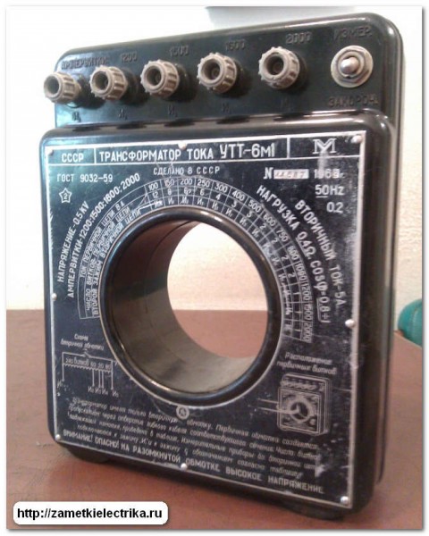
Now I will not dwell on it in detail. I will talk about it in a separate article. For those who are interested, you can subscribe to articles (in the right column of the site) and receive a notification by mail about the release of a new article on the site.
Classification of current transformers at the place of installation
According to the place of installation of current transformers, they can be classified as follows:
outdoor
domestic
built-in
portable
special
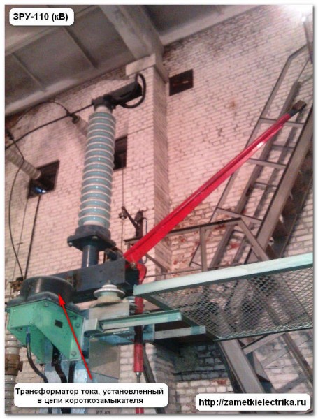
Outdoor current transformers can be installed outdoors, i.e. it can be an open switchgear (ORU). The category of placement of electrical equipment in this case is I and is regulated by GOST 15150-69.
The photo below shows outdoor CTs installed on the 110 (kV) side.

Internal current transformers may only be installed indoors. This can be a closed switchgear (ZRU), and a complete switchgear (KRU), as well as all rooms of a closed type, regulated by GOST 15150-69.
An example of the internal installation of current transformers, see the photographs below.
Here is the installation of a high-voltage current transformer TPSHL-10 in ZRU-110 (kV). This transformer is in.
The photo below shows an example of installing high-voltage current transformers TPL-10 in the cable compartment of a switchgear cell with a voltage of 10 (kV).

These are TPFM-10 transformers at one of the 10 (kV) distribution substations.

And these are a few examples of low-voltage current transformers for indoor installation: KL-0.66 and TTI-A.

![]()
Built-in current transformers are built into power transformers, switches, generators and others electric cars. Transformer oil or gas is used as the internal medium of electrical equipment.
You can see an example of built-in CTs in the photo below. These TVT current transformers are built into the tank of a 110/10 (kV) power transformer with a capacity of 40 (MVA). They are installed on the 110 (kV) side and the main purpose of their installation is to implement differential protection of the transformer.
![]()
![]()
Portable CTs are used for laboratory electrical measurements and testing of electrical equipment. An example of a portable current transformer is the laboratory current transformer, which I talked about at the very beginning of the article.
Special CTs are intended and installed in special electrical installations mines, ships, electric locomotives. This includes current transformers installed in the power supply circuit of electric furnaces. high frequency. I personally have never seen them with my own eyes.
Separation of CTs by installation method
According to the method of installation of current transformers, they can be classified as follows:
walk-through
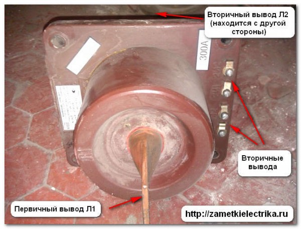
Pass-through CTs are used when it is necessary to install them in the opening of a wall or a metal surface (base). Most often they are used as inputs, as well as at old substations with a concrete switchgear (CRU), due to the design features of concrete partitions. Bushing current transformers play the role of a bushing insulator.

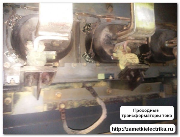
As can be seen from the photographs, feed-through current transformers are easy to recognize by the location of the primary winding terminals. One pin is always at the top, the other at the bottom.
Support current transformers are used and installed on a flat reference plane.
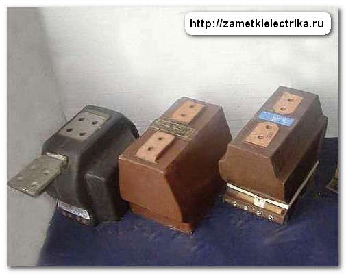
A distinctive feature of reference current transformers is that the outputs of the primary winding are located either all at the top, or one output on the left, the other on the right.
Classification of current transformers by transformation ratio
What is the classification of current transformers according to the transformation ratio?
Current transformers are:
with one constant transformation ratio (single-stage)
with several transformation ratios (multi-stage)
Current transformers with one have one constant coefficient throughout their entire service life and operation, which cannot be changed in any way. They found the most wide application.

For current transformers with several transformation ratios, this ratio can be changed by simple manipulations. For example, change the number of turns of the windings, both primary and secondary.
Again, as an example, I give you my laboratory current transformer UTT-6m1.
Classification of current transformers by primary winding
According to the design of the primary winding, current transformers can be divided as follows:
with one turn (single turn)
with several turns (multi-turn)
We will talk about this with you in a separate article about, because. there is a lot of material on this topic.
Separation of CTs by type of insulation
The essence of this separation lies in the methods of insulating the windings of the current transformer (primary and secondary). There are the following ways to isolate the windings from each other:
- solid insulation
- viscous insulation
- mixed insulation
- gas insulation
Solid insulation refers to the use of porcelain, polymeric materials, bakelite, nylon and epoxy insulation (resin).
Viscous insulation consists of compounds of various compositions.
Mixed insulation is oil-paper insulation.
Air or SF6 is used as gas insulation.
CT classification by conversion method
The classification of current transformers according to the conversion method lies in the very principle of converting alternating electric current.
There are the following conversion methods:
electromagnetic
optoelectronic
Classification of current transformers by voltage class
Well, we got to the voltage class. And of course, current transformers are also divided into them. The division is very easy and simple:
voltage class up to 1 (kV)
voltage class from 1 (kV) and above
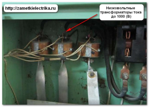
![]()
The difference in voltage class of current transformers is visible to the naked eye.
conclusions
From the experience of operation and maintenance of current transformers at the substations of my enterprise, I will say that most often current transformers with a voltage class of 3-10 (kV) are made through, less often as reference ones. All of them are designed for indoor installation and have the same transformation ratio. They also use 2 secondary windings, one of which is used for measuring and metering circuits of electricity, and the other for relay protection.
P.S. If you need to know all the classification, then use his passport. If you have any questions while reading the article, feel free to ask them in the comments.
A voltage transformer is one of the types of transformers, which is also called measuring, designed to separate the primary circuits of high and extra high voltages and measurement circuits, RZ and A. They are also used to lower high voltages (110, 10 and 6 kV) to standard normalized secondary winding voltages - 100 or 100 / √3.
In addition, the use of voltage transformers in electrical installations makes it possible to isolate low-power low-voltage measuring instruments and devices, which reduces the cost and allows the use of simpler equipment, and also ensures the safety of electrical installation maintenance.
Voltage transformers are widely used in high-voltage power electrical installations, the accuracy of their operation determines the correct commercial accounting of electricity, the selectivity of the operation of relay protection devices and emergency automation, they also serve to synchronize and power the automation of relay protection of power lines from short circuits, and etc. 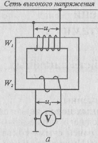
Device. The principle of operation of the HP
Measuring transformer structurally practically does not differ from standard power transformers. It consists of windings: primary and one or more secondary and a steel core, recruited with sheets of electrical steel. The primary winding has more turns than the secondary. The voltage to be measured is applied to the primary, and the wattmeter and other measuring devices are connected to the secondary. Since the wattmeter has a significant resistance, it is customary to assume that a small current flows through the secondary. Therefore, it is believed that the measuring voltage transformer operates in modes close to idle.
Such transformers are equipped with connectors for connection: the primary winding is connected to the circuits power voltage, and relays, windings of a voltmeter or wattmeter, etc., can be connected to the secondary. Their operating principle is similar power transformer: voltage transformation into measuring transformer produced by an alternating magnetic field.
Magnetization losses cause some error in accuracy classes. The error is determined:
The design of the magnetic circuit;
steel permeability;
- power factor , i.e. depends on the secondary load.
The design provides for voltage error compensation by reducing the number of turns of the primary winding, eliminating the angular error using compensating windings. 
The simplest circuit for switching on a voltage transformer
HP classification
Voltage transformers are usually divided according to the following criteria:
By the number of phases:
Single-phase;
Three-phase.
By number of windings:
2-winding;
3-winding.
3. According to the mode of operation of the cooling system:
Oil-cooled electrical devices;
Electrical devices with an air cooling system (cast resin or dry).
4. According to the installation and placement method:
For outdoor installation;
For internal;
For complete switchgear.
5. According to the class of accuracy: according to the normalized values of errors.
Consider several voltage transformers from different manufacturers:
 1. Voltage transformer ZNOL-NTZ-35-IV-11
Manufacturer
Nevsky transformer plant "Volkhov".
Purpose and scope of ZNOL-NTZ
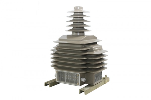
Transformers are designed for outdoor installation in open switchgears(ORU). Transformers provide signal transmission of measurement information to measuring instruments and protection and control devices, designed for use in commercial electricity metering circuits in electrical installations alternating current for voltage class 35 kV. The transformers are made in the form of a supporting structure. The transformer housing is made of a compound based on Huntsman hydrophobic cycloaliphatic resin, which is also the main insulation and provides protection of the windings from mechanical and climatic influences.
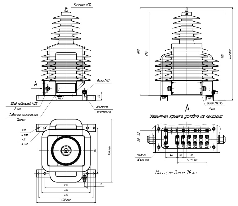
Picture - dimensions transformer 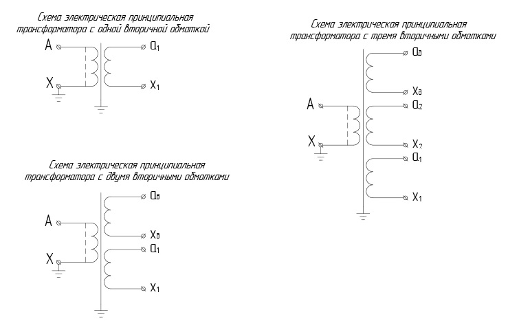
Figure - connection diagrams of transformer windings
Characteristics:
Voltage class according to GOST 1516.3, kV - 27 35 27
Maximum operating voltage, kV - 30 40.5 40.5
Rated voltage of the primary winding, kV - 15.6 20.2 27.5
Rated voltage of the main secondary winding, V - 57.7 100
Rated voltage of additional secondary winding, V - 100/3, 100 127
Nominal accuracy classes of the main secondary winding - 0.2; 0.5; one; 3 
2. Three-phase antiresonant group of voltage transformers 3xZNOLPM(I) - manufacturer "
Sverdlovsk Plant of Current Transformers"
Purpose3xZNOLPM(I)
Transformers are designed for installation in complete devices (KRU), current ducts and serve to power measurement, protection, automation, signaling and control circuits in electrical installations of alternating current with a frequency of 50 or 60 Hz in networks with isolated neutral.
Transformers are manufactured in climatic version "UHL" category 2 according to GOST 15150.
Working position - any.
The location of the primary output is possible both from the front and from the back of the transformer.
The three-phase group can be completed in 4 versions:
Of the three transformers ZNOLPM - 3xZNOLPM-6 and 3xZNOLPM-10;
Of the three transformers ZNOLPMI - 3xZNOLPMI-6 and 3xZNOLPMI-10;
From one ZNOLPM transformer (installed in the middle) and two ZNOLPMI transformers (installed along the edges) - 3xZNOLPM (1) -6 and 3xZNOLPM (1) -10;
Of the two ZNOLPM transformers (installed at the edges) and one ZNOLPMI transformer (installed in the middle) - 3xZNOLPM (2) -6 and 3xZNOLPM (2) -10.
To improve resistance to ferroresonance and intermittent arcing, it is recommended to include a 25 ohm resistor with a continuous current of 4A in additional windings connected in an open delta, used to control network insulation.
Attention! When ordering voltage transformers for AISKUE, it is mandatory to fill out a questionnaire.
The warranty period of operation is 5 (five) years from the date of putting the transformer into operation, but not more than 5.5 years from the date of shipment from the manufacturer.
Service life - 30 years. 
3. NAMIT-10-2 - manufacturerJSC Samara Transformer
Purpose and scope
The voltage transformer NAMIT-10-2 UHL2 three-phase oil antiresonant is a scale converter and is designed to generate a measurement information signal for measuring instruments in metering, protection and signaling circuits in 6 and 10 kV AC industrial frequency networks with isolated neutral or grounded through an arcing reactor. The transformer is installed in switchgear cabinets (N) and in closed switchgear of industrial enterprises
Technical parameters of the voltage transformer NAMIT-10-2
Rated voltage of the primary winding, kV - 6 or 10
The highest operating voltage, kV - 7.2 or 12
Rated voltage of the main secondary winding (between phases), V - 100 (110)
- voltage of additional secondary winding (аД - xД), no more than, V - 3
Accuracy class of the main secondary winding - 0.2 / 0.5
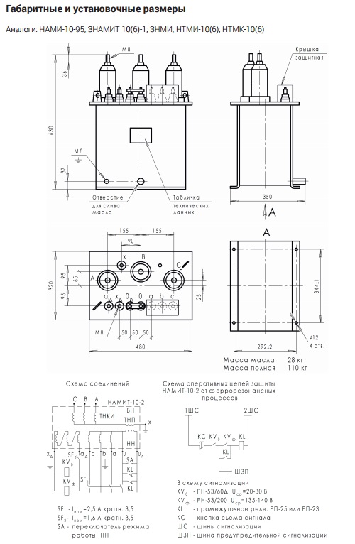
Figure - Overall dimensions and wiring diagram