Active power of a three-phase system R is the sum of phase active powers, and for each of them the basic expression of the active power of alternating current circuits is valid. Therefore, phase active power R f =WU f I f cos and with a symmetrical load active power three-phase device
P=3P F = 3U F I F cos (3.7)
But in three-phase installations, in most cases, it is necessary to express the active power of the device not in terms of phase, but in terms of linear quantities. This is easy to do on the basis of the ratios of phase and linear values, replacing the phase values in the expression of active power with linear ones. When connected by a star U F = U L / 3 ; I F = I L, and when connected by a triangle U F = U L ; I F =I L / W.After substituting these expressions into formula (3.7), we obtain the same expression for the active power of a three-phase symmetrical installation:
P = 3 U F I F cos = 3 U L I L cos
Although this expression refers only to the active power of a symmetrical system, it can nevertheless be used as a guide in most cases, since in industrial devices the main load is rarely unbalanced.
Reactive power in a symmetrical system, as well as apparent power, is expressed in terms of linear quantities, like active power:
Q = 3 Q F = 3 U F I F sin = 3 U L I L sin
S = 3 U F I F = 3 U L I L
The simplest conditions for measuring the active power of a three-phase system are available if the phases of the receivers are connected in a star with an accessible neutral point. In this case, to measure the power of one phase, the current circuit of the wattmeter is connected in series with one of the phases of the receiver (Fig. 3.12a), and the voltage circuit is connected to the voltage of that phase of the receiver in which the current circuit of the wattmeter is connected, i.e., the clamps of the voltage circuit of the wattmeter one is connected to the line wire, and the second to the neutral point of the receiver. Under such conditions, the measured power
P FROM = P F = U F I F cos
and the power of the symmetrical receiver
P =3 P FROM =3 U F I F cos
Often the neutral point is not available or the receiver phases are delta connected. Then a measurement is applied using an artificial neutral point (Fig. 12 b).
Rice. 3.12 Scheme for measuring active power in a symmetrical three-phase system:
a - with an accessible neutral point,
b - with an artificial neutral point
Such a point (more precisely, a node) is made up of a wattmeter voltage circuit with resistance r Tue . n and two additional resistors FROM the same resistance. With this connection, the voltage circuit of the wattmeter is under phase voltage, and the phase current passes through the current circuit of the device. Therefore, even with this measurement
P = 3 P FROM
To measure active power in a four-wire installation (i.e., an installation with a neutral wire) with an unbalanced load, the method of three wattmeters is used (Fig. 3.13). In such an installation, each of the wattmeters measures the active power of one phase, and the active power of the installation is determined as the sum of the powers measured by three wattmeters:
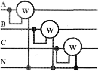
Rice. 3.13 Scheme for measuring active power in a three-phase four-wire system (three-wattmeter method)
In three-wire networks with an unbalanced load, power is measured by the method of two wattmeters.
If you include two wattmeters in a three-wire system direct current(Fig. 3.14), they will measure the power of the entire installation. It does not matter what the voltages of the individual circuits are combined in a three-wire system. If, instead of constant current and voltage, we consider the instantaneous values of the voltages and currents of a three-phase system, then under such conditions the wattmeters will show the average values of instantaneous powers, i.e. active powers. But it should be kept in mind that although P =P 1 + P 2 , the power of the system is equal to the sum of the readings of two wattmeters, but this sum is algebraic, i.e. the reading of one of the wattmeters can be negative - the arrow of one of the wattmeters can deviate in the opposite direction, beyond the zero of the scale. In order to read the wattmeter reading under such conditions, you need to switch the clamps of the voltage circuit. The readings of the device after such a switch should be considered negative.

Rice. 3.14 Scheme for measuring active power in a three-phase three-wire system (two wattmeter method)
Example. Three-phase symmetrical power consumer with phase resistance Za =Zb =Zc = Zf =R= 10Ohm connected by a "star" and included in a three-phase network with symmetrical line voltage Ul= 220AT(fig.3.15). Determine the currents in the phase and linear wires, as well as the consumed active power in the modes:
a) with a symmetrical load;
b) when the line wire is disconnected;
c) in case of short circuit of the same load phase.
Build topographic voltage diagrams for all three modes and show the current vectors on them.

a) decision. Phase voltages with symmetrical load: Ua = Ub = Uc = Uf=Ul/3 = 2203 = 127AT. Phase currents at this load: I F =Uf/Rf= 127/10 = 12,7BUT. Linear currents with symmetrical load: I BUT = I C = I L = I f = 12,7BUT, since a symmetrical three-phase power consumer is connected by a "star".
Active power of a three-phase symmetrical consumer: R=3Rf=3 UfIfcos = 312712,71 = 4850Tue= 4,85kW or R=3UlIlcos f =322012,71 = 4850Tue= 4,85kW, where cos f= 1 at Z F =R F .
The vector diagram of voltages and currents is shown in Fig. 3.16.

b) Solution Current in line wires aa and ss in the event of a line break LB(switch S open); since the phase resistance Zb=(I AT =0 ), a Za=R and Zc=R connected in series to line voltage U CA =U L = 220B;I A =I C =I=U CA /(R+R) = 220/(10 + 10) = 11BUT.
Voltage on the phases of the consumer in the event of a break in the linear wire LB(neutral point P in this case corresponds to the middle of the vector line voltageU CA):Ua=Uc=U CA /2 = 220/2 = 110 B.

Voltage between phase wire AT and neutral point P determined from the vector diagram (Fig. 3.17): Uc=Ul cos/6 = 2200.866 = 190.5 B.
Active power of the consumer in the event of a line wire break LB:R=R BUT +R FROM = 2I 2 R F = 211 2 10 = 2420Tue= 2,42kW.
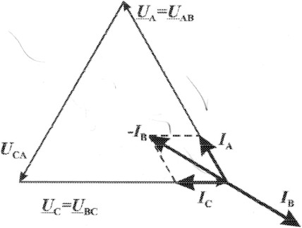
c) For the condition of the problem, determine phase voltages U F and currents I F, active power Rk consumer in the event of a phase short circuit Zb, build a vector diagram for this case fig. 3.18.

Solution. In this case Zb=0 and Ub=0 , neutral point P move to a point AT, while the phase voltages Uc =U BC ,U a =U AB, i.e. phase voltages are equal to line voltages ( Uf=U L). In this case, the phase currents: I A =I C =Ul/R= 220/10 = 22BUT. Current I AT at short circuit according to Kirchhoff's first law for the neutral point P:I A +I B +I C = 0 or - I B =I A +I C .
From a right triangle in the vector diagram fig. 3.19 we have: (- I B /2) 2 + (I A /2) 2 =I 2 And where from I B =3I A =322≅38BUT. Wherein I BUT =U L /Za=IWith=U L /Zc=Ul/R= 220/10 = 22BUT.
Active power of the circuit in case of short circuit: Rk=R BUT +P C = 2I 2 fR= 222210 = 9680Tue= 9,68kW. The vector diagram of voltages and currents is shown in fig. 3.19
Active power of a three-phase symmetrical receiver electrical energy consists of three components
where R AF is the active power of the electrical energy receiver in phase A.
With phase symmetry synchronous generator and loads
where R f is the active power of one phase of the receiver.
From expressions (10.5) and (10.6) it follows:
For the star schema:
![]() (10.8)
(10.8)
Using expressions (10.7) and (10.8) for the "star" scheme, we obtain:
For the "triangle" scheme:
 (10.10)
Usually in three-phase circuits operate with linear values of currents and voltages, so the index "l" is usually removed. Expressions for active, reactive and full capacity look like:
 (10.11)
End of work -
This topic belongs to:
HISTORY OF THE POWER INDUSTRY
State educational institution... Supreme vocational education... Omsk State Technical University...
If you need additional material on this topic, or you did not find what you were looking for, we recommend using the search in our database of works:
What will we do with the received material:
If this material turned out to be useful for you, you can save it to your page on social networks:
| tweet |
All topics in this section:
Lecture 3. Electric current. Electric field
Electric current is the ordered movement of electric charges. For the emergence electric current it is necessary (Fig. 3.1): 1) the presence of free charges;
source emf electrical energy is numerically equal to the work of external forces to move a single positive charge from the negative to the positive source pole, i.e.
Constant and instantaneous values of current, voltage and EMF
Since current, voltage, EMF can be constant and variable, various designations are used to reflect this fact. Instantaneous values of current, voltage, EMF are usually denoted
Lecture 5. Idealized elements of an electrical circuit
Table 5.1 Idealized elements of the electrical circuit No. Name of the idealized element Graphic image Letters
AC Specifications
For an unambiguous description of processes in an electrical circuit, it is necessary to know not only the value of quantities, but also the direction of these quantities. The direction of the current is taken to be the movement along
Kirchhoff's second law
The algebraic sum of voltage drops in any closed circuit is numerically equal to the algebraic sum of the EMF acting in this circuit:
Vector diagram method
This method is used to better understand and visualize the representation of a process that changes according to a harmonic law. The essence of the method: variables
Lecture 7. The effective value of alternating current. The relationship between current and voltage in the elements of the electric current circuit
effective value alternating current is equal to such a value of direct current, which, in a time equal to the period of alternating current, releases in the same resistance the same amount
Active resistance
Let there be an alternating current circuit (Fig. 7.3).
Inductance
Rice. 7.5. Electric circuit c induct
Capacity
Rice. 7.7. Electrical circuit with capacitance
Lecture 9
From the definition of the potential difference it follows that the work electric field on the movement of a positive charge from point A with a potential
Lecture 10. Three-phase electrical circuits
An electrical circuit in which one EMF operates is called single-phase. Polyphase electrical circuits- these are circuits in which there are several EMFs of the same frequency, shifted relative to
The principle of operation of a synchronous generator
When the rotor rotates, its magnetic field crosses the turns of the stator and, according to the law of electromagnetic induction, induces EMFs in them, shifted relative to each other in phase by 120 ° (Fig. 10.1). &nb
Communication of linear voltage with phase
Let us assume that we are considering a symmetrical three-phase system, i.e.
Relationship between line and phase current
Let's consider a part of the above diagram (Fig. 10.4) related to phase A. It follows from the figure that IAF = IA. Similarly, IHF \u003d IB, ISF \u003d IC
The principle of operation of the transformer
When the primary winding is connected to a voltage u1, an alternating current i1 arises in the winding, which creates an alternating magnetic flux Ф1 in the core. This magnetic
Transformer ratio
It follows from the theory of transformers that U1 ≈ E1. We divide expressions (11.2) by (11.3):
Self-regulation of the magnetic flux by a transformer
When operating a transformer in power supply systems, the following conditions are met: ƒ = const, U1 = const. Voltage deviation
Three-phase power transformers
Subdivided: · into group; three-rod. Group transformers are transformers with a core separate for each phase (Fig. 11.3).
Energy diagram of a transformer
Consider a single-phase two-winding transformer.
Load Efficiency
To describe this dependence, a concept is introduced - the load factor of the transformer, which is determined by the formula
Lecture 13
Electric cars- These are electrical devices designed to convert electrical energy into mechanical energy (engine), or mechanical energy into electrical energy (generator).
Lecture 14
It follows from the laws of Ampere and Faraday that these laws can be put in the basis of the principle of operation of any electric machine. It follows from them that in any electric machine there must be
AC electrical machines
AC machines include synchronous and asynchronous machines. Synchronous machines are electrical machines in which the rotating magnetic field of the stator and rotor
Structural design of AC electrical machines
The stator of AC electrical machines carries two or three-phase winding, which is connected respectively to two or three-phase network alternating current. Purpose
The design of the rotors of electrical AC machines
Alternating current electric machines differ mainly in the design of the rotor. The rotors of synchronous machines are made of electrical steel and are subdivided
Rotors of asynchronous machines
squirrel-cage rotor It is recruited from plates of electrical steel, isolated from each other. There is a winding in the grooves. If you make a section perpendicular to the axis of the rotor, you get the following
Lecture 15
When the stator winding is connected to an alternating current network, a rotating magnetic field almost instantly appears in the stator.
Single phase asynchronous motor
Consider wiring diagram single-phase asynchronous motor with one winding on the stator. single phase asynchronous motor is an asynchronous motor connected to single-phase network variable
Lecture 16
A DC machine is an electrical device that is combined into a single design synchronous machine(SM) and switch (K). The switch is an electrical element
The principle of operation of the DC generator
When the armature rotates at a speed ω from any external device, an EMF is induced in the conductors according to the law of electromagnetic induction, and since the winding is closed to the load, something flows through it
Lecture 17. DC machines
Valve DC generator Principle of operation. When the inductor rotates in the conductors of the armature winding, according to the law
Lecture 18
The number of poles of the inductor is four. Introduced p - the number of pairs of poles. For this stator, p = 2, and 2p = 4;
DC motor speed control
1. The equation for the balance of voltages in the armature circuit (see (17.10) has the form
Anchor way
Let UС change as follows: (we reduce the voltage), since at
Pole regulation
Let Φ change according to the inequality ΦNOM > Φ1 > Φ2. it follows from the equation that with a decrease in F, the coefficients A and B increase, and IP \u003d const. T
Rheostatic regulation Lecture 20 current transformer Features of the operation of current transformers Measuring voltage transformers Lecture 21. Power supply systems. Definitions, terminology. The principle of building power supply systems Lecture 23 Lecture 24 When energy saving Lecture 25. Maxwell's equation. Vortex electric field. Bias current Displacement current features Lecture 26 Electric field strength inside the capacitor Lecture 28 Goals and objectives of the discipline It is recommended to print this material for your convenience. Recommendations for passing the test and exam SEMESTER SEMESTER EXAMINATION TICKET No. 10 EXAMINATION TICKET No. 25 Technical means of training and control. An electric current whose magnitude and direction change at regular intervals is called changenym.
Such a current is conventionally denoted by the sign ~. Alternating current, unlike direct current, which always has one direction and does not change its magnitude, changes according to a sinusoidal law This current is obtained from alternators. The diagram of the simplest alternator is shown in the figure below: Between the poles N and
S
electromagnet rotates steel cylinder BUT, on which a frame made of insulated copper wire is fixed. The ends of the frame are attached to copper rings isolated from the shaft. Fixed brushes are pressed against the rings SCH, which are connected by wires to the power receiver R.
As the frame rotates, it crosses the lines of force of the magnetic field, and electromotive forces are induced in each of its sides, which, summing up, form a common electromotive force. With each revolution of the frame, the direction of the total electromotive force is reversed, since each of the working sides of the frame passes under different poles of the electromagnet in one revolution. The electromotive force induced in the frame also changes, as the speed at which the sides of the frame intersect the magnetic field lines changes. Therefore, with a uniform rotation of the frame, an electromotive force will be induced in it, periodically changing in magnitude and direction. If fixed brushes SCH, wired to a power receiver R,
form a closed electrical circuit, then an alternating single-phase current will flow from the energy source to the receiver. The time during which an alternating current completes a full cycle of changes in magnitude and direction is called period.
It is denoted by the letter T and is measured in seconds. The number of cycles per second is called frequency
alternating current. It is marked with the letter f
and is measured in hertz. Since the frequency indicates the number of complete cycles of current change in magnitude and direction in one second, the period is defined as the quotient of one second divided by the frequency: T=1/f,
f=1/
T.
In engineering, alternating currents of various frequencies are used. In Russia, all power plants generate AC power of standard frequency - 50 Hz. This current is called industrial frequency current and is used to supply electricity to industrial enterprises and for lighting. Receiving three-phase alternating current. In technology, three-phase alternating current is widely used. Three-phasecurrent called a system consisting of three single-phase currents of the same frequency, shifted in phase by one third of the period relative to each other and flowing through three wires. Three-phase current is obtained in a three-phase generator that creates three electromotive forces shifted in phase by an angle of 120° (one third of the period). The simplest three-phase current generator is a ring-shaped steel core on which three windings are located: ω
1
,
ω
2
and ω 3
,
shifted one relative to the other along the circumference of the core by 120 °. The core with windings is called stator
generator, and an electromagnet rotating inside the stator - rotor.
The rotor winding, called the excitation winding, carries a direct current that magnetizes the rotor, forming a north N and south S poles. When the rotor rotates, the magnetic field created by it crosses the stator windings, in which an electromotive force is induced. The magnitude of the electromotive force depends on the speed at which the magnetic field lines of the rotor cross the magnetic field of the stator. The poles of the rotor and the stator windings must be such that in each of the stator windings a sinusoidal electromotive force occurs, shifted in phase by 120 °. If a load is connected to each of the three windings of the generator, then the result will be three single-phase alternating current circuits. If the resistances of consumers are equal, the amplitudes of the currents in each circuit will be equal to each other, and the phase relationships between the currents will be the same as between the electromotive forces in the generator windings. Each of the generator windings, together with the external circuit connected to it, is commonly called phase.
In order to form a single three-phase system from these independent single-phase systems, it is necessary to connect separate windings. The generator windings can be connected in two ways: star and delta. When connecting the star windings of the generator and consumers (Fig. 58), four wires are used instead of the six required in an uncoupled system. Reducing the number of wires increases the efficiency of the power transmission line device. Three wires from the generator windings to receivers /, //, III,
called linear, since they make up a line for transmitting energy from the generator to the receivers, and the wire connecting the common points of the generator and consumer phases is zero. If the loads of all three phases are the same in magnitude, then the total current in the neutral wire will be zero. However, a uniform load can only be ensured when three-phase consumers are powered, connected and disconnected by all three phases simultaneously. Single-phase consumers are switched on independently of one another, and when they are powered, full phase load uniformity cannot be achieved. In this case, the neutral wire must maintain the equality of different consumer voltages The voltage between the linear wires is called linear, and the voltage in each phase is called phase. When connected by a star, the linear current is equal to the phase current, and the phase voltage is 1.73 times less than the linear voltage with the same phase load. Single-phase receivers, such as incandescent lamps, can be connected directly to line wires for line voltage (Fig. 59). Such a connection is called a triangle connection. This connection is used for lighting and power loads. The phases of a three-phase generator are connected as follows: the end of the first phase with the beginning of the second, the end of the second with the beginning of the third and the end of the third with the beginning of the first, and line wires are connected to the phase connection points. Since the phases of the consumer or generator with such a connection are connected directly to the linear wires, their phase voltages are equal to linear, i.e. Uf=
Ul, and the linear currents are 1.73 times larger than the phase currents in absolute value with the same phase load. The delta connection of generator windings is quite rare. In three-phase current motors, the ends of the windings can be connected in a star or a delta. AC power. The main value in electrical calculations is the average, or active, power. It is calculated according to the formula: Pa=
IfUfcosφ
Tue where If- phase value of the current, a; Uf
- phase value of voltage, in; φ
- phase angle between current and voltage. With a uniform load of a three-phase system, the power consumed by each phase is the same, so the power of all three phases Pa=3
IfUfcosφ
Tue The active power of three-phase alternating current when connected with a star and a delta is determined by the formula Pa=1,73
IlUlcosφ
Tue The concept ofcosφ
and measures to increase it. In addition to active power, there is reactive power in the electrical circuit. Active and reactive power make up the apparent power S. Active power R a is consumed in the circuit when heat is released or useful work is done, and the reactive R p- with increasing current to create magnetic fields in the inductive part of the circuit. When the current decreases, the circuit becomes, as it were, a generator, and the energy stored in it is transferred to the generator that feeds this circuit. Such a movement of energy from the generator to the circuit and back loads the line and the generator winding, causing unnecessary energy losses in them. The ratio of active power to apparent power is called power factor.
It shows how much of the apparent power is actually consumed by the circuit and is calculated using the formula Withosφ=Uicosφ/UI=
R a/S. Thus, the power factor for a sinusoidal alternating current is the cosine of the phase angle between current and voltage. The increase in cos φ depends on the type, power and speed of newly installed engines, increasing their load, etc. The concept of the thermal effect of current. When current passes through a conductor, the latter heats up. The Russian academician E. X. Lenz and the English physicist D. P. Joule simultaneously and independently of one another established that when an electric current passes through a conductor, the amount of heat released by the conductor is directly proportional to the square of the current, the resistance of the conductor and the time during which the current flowed through the conductor. This position is called the Joule-Lenz law and is determined by the formula: Q
= 0,24I 2
Rt, where Q
- quantity of heat, feces; I- the current flowing through the conductor, a; R
- conductor resistance, ohm; t
- time, sec. To protect electrical devices from excessive heating, low-melting fuses are included in the electrical circuit, and a thermal maximum relay is used to protect electric motors during current overloads. Electrical measuring instruments. Electrical measuring instruments are used to measure various electrical quantities: current, voltage, resistance, etc. According to the type of measured value, the instruments are divided into ammeters that measure current, voltmeters that measure voltage, ohmmeters that measure resistance, etc. Electrical measuring instruments consist of moving and fixed parts. An index arrow is attached to the moving part of the device, which is used to read the measured value on a fixed scale. The essence of the operation of an electrical measuring instrument is that the current passing through its coils causes the movable part of the instrument to rotate, as a result of which the arrow deviates at a certain angle. Ammeters that measure current in an electrical circuit are connected in series, and voltmeters are connected in parallel. According to the type of current, devices are divided into devices that measure only alternating or direct current, and devices that measure both alternating and direct current. Electrical measuring instruments are divided into seven accuracy classes: 0.1; 0.2; 0.5; one; 1.5; 2.5 and 4. The figure of the accuracy class indicates the value of the main permissible error of the instrument from its largest indication. So, if the voltmeter is rated at 150 in, and its accuracy class is 2.5, then when measuring voltage with this device, the possible error will be 2.5%.
Let RD change as follows: RD START
Measuring current and voltage transformers are used to convert and transmit electrical signals from the primary (power) circuit to the secondary (low current) circuit. As a result of the chain
The current transformer (Fig. 19.1) consists of a core made of high-quality sheet electrical steel, the primary winding with the number of turns W1, the secondary
It is known that power transformers have the property of self-regulation of the magnetic flux of the core Фс (Fig. 19.2), otherwise you can write Фс = Ф1 - Ф
Voltage transformers are used to power the winding of a voltmeter and relay in AC devices at a voltage of U ≥ 380V. The voltage transformer consists of a core
Electrical installations are called electrical machines, lines and auxiliary equipment (together with the structures and premises in which they are installed) intended for
The construction of power supply systems is carried out according to a number of basic principles. These principles can be grouped or formulated as follows: 1. Maximum source approximation
Energy saving is: 1) increase in production; 2) increase in incomes of the population; 3) environmental protection. In Ros
1. Energy certification of all enterprises, regardless of ownership. The presence of an energy passport allows you to reduce the cost of paying for energy resources by almost
The cost of energy resources is formed at the enterprise from the payment for electrical, thermal energy and direct use fuel. In some cases, this includes compressed air, steam, etc.
From Faraday's law: , (23.1) it follows that the change
3. Any change in the electric field causes the appearance of a vortex magnetic field in the surrounding space. 4. Since the source of the magnetic field is an electric current, the change
Let's consider an electric circuit of alternating current: Fig. 23.1 - Elect
; (24.1)
, (24.5) where
The issue of reactive power compensation is one of the main issues to be resolved both at the design stage and at the stage of operation of industrial power supply systems, including
This discipline is designed to confirm the correctness of students' choice of their future profession, to arouse interest in studying other disciplines related to electricity, electrical engineering, electric power
To prepare for the exam and test it is necessary: 1. To be able to answer control questions (see the file "Control questions"). To prepare answers to security questions
To stimulate the systematic work of students during the semester, training in the 1st year is carried out according to the module-rating system. The main points of this technique are set out in d
1 week of midterm control October 12-17: Practical work (additional) (2.4 points)
1 week of midterm control March 15-20: Practical work (additional) (2.4 points)
1. Self-regulation of the magnetic flux of the transformer. (L.12 for.11.15 p.41, see also for. 11.1-11.11 p.39-40) 2. Determination of the electric field strength. Electro potential
1. Relationship between current and voltage on inductance. (L.7 fig.7.5-7.6 for.7.19-7.27 p.24-25, know the 2nd Kirchhoff's law L.6 for.6.2 fig.6.3 p.17-18, Faraday's law L.13 for. 12.7- 12.9) 2.
5.1.1 Use of educational posters. Posters: 1. Electrical resistance. 2. Series connection of a resistor and a capacitor. 3. Serial connection cut