Operating principle (on the example of a parallel excitation motor). If voltage U is applied to the motor, then current I c flows through the excitation circuit, and current I i flows through the armature circuit. The excitation current creates MMF F in = I in W in, which excites the magnetic flux in the machine F in. The armature current, in turn, creates a magnetic flux of the armature reaction F i. The resulting magnetic flux F res \u003d F in + F i.
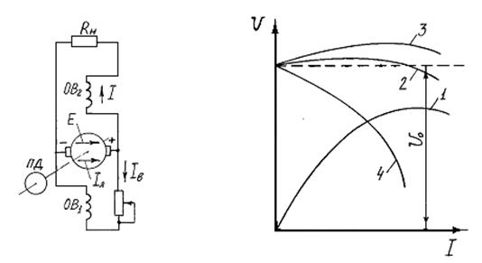
Fig.1.23 1.24
In the armature circuit, the current I i creates a voltage drop R i I i. In accordance with the law of the electromagnetic force EMC, when the current I I and the magnetic flux F res interact, a torque M BP is created. In steady state M temp. \u003d M pr. When the armature conductors cross the magnetic field F res, in accordance with the law of electromagnetic induction EMP, an EMF is induced in them, which is directed against the mains voltage U.
Classification of engines. According to the circuit for switching on the excitation windings of the main poles, the motors direct current are divided into engines of independent, parallel, sequential and mixed excitation.
In independent excitation motors, the field winding is powered by a separate DC voltage source. In parallel excitation motors, the field winding and the armature winding are connected in parallel and are powered from the same source. In series and mixed excitation motors, there is an excitation winding connected in series with the armature winding. In low power motors, the excitation flux can be created using permanent magnets. Motors of parallel and mixed excitation find the greatest application.
Basic equations and quantities characterizing engines. These values are: mechanical power on the shaft R 2, the supply voltage U, the current consumed from the network I, the armature current I I, the excitation current I in, the rotational speed n, the electromagnetic moment M em. The relationship between these quantities is described:
Ø electromagnetic torque equation:
M em \u003d C m I I F;
Ø equation electrical state anchor chains:
U \u003d E pr + R i I i; (1.4)
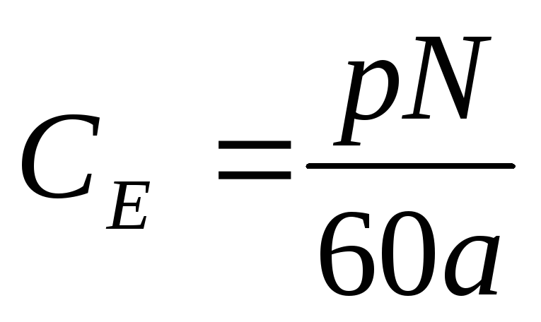
E pr \u003d C E nФ;
Ø moment equation:
M em \u003d M s + M sweat + M d,
where M s is the moment of resistance on the shaft created by the load; M sweat - the moment of losses created by all types of losses in the engine; M d - dynamic moment created by inertial forces;
Characteristics of engines. The most important of the characteristics is mechanical n (M s) - the dependence of the rotational speed n on the torque on the shaft (hereinafter, the index "c" is omitted) at U = const, I в = const. It shows the influence of the mechanical load (torque) on the motor shaft on the speed, which is especially important to know when choosing and operating motors. Other engine characteristics: adjusting n (I c), high-speed n (I i), working M, R 1, n, I, h (R 2) - are not considered in detail here.
Mechanical characteristics can be natural or artificial. Under natural characteristics are understood as characteristics taken in the absence of any additional resistances in the circuit, for example, rheostats in armature or excitation circuits, artificial- in the presence of such resistances.
Mechanical equationengine characteristics. It can be obtained from (1.1). We substitute instead of E its value in (1.4), then
n \u003d (U - R i I i) / C E F. (1.5)
Replacing I i with its value from (1.2), we obtain the equation mechanical characteristics:
n= ![]() (1.6)
(1.6)
The type of mechanical characteristic is determined by the nature of the dependence of the flux on the motor load, which in turn depends on the circuit for switching on the excitation winding.
Engine reversal. Engine reversal is understood as a change in the direction of rotation of its armature. Possible ways of reversing follow from relation (1.2). If you change the direction of the armature current or the flow of the machine, then the sign, and therefore the direction of the torque, changes. In practice, this is achieved by switching the leads or the armature winding, or the excitation winding. However, simultaneous switching of the outputs of both windings or a change in the polarity of the voltage supplying the motor (except for an independent excitation motor) does not lead to a change in the sign of the torque and, therefore, to a change in the direction of rotation.
Starting the enginesdirect current. There are two main requirements for starting the engines: to provide the torque necessary for starting and accelerating the armature and to prevent excessive flow through the armature during start-up. high current dangerous for the engine. Three methods of starting are practically possible: direct start, start when a rheostat is connected to the armature circuit, and start with undervoltage in the anchor chain.
With direct starting, the armature circuit is immediately switched on to full voltage. Since at the first moment of starting the armature is stationary (n = 0), there is no back-emf (E pr = C E nF). Then from (1.4) it follows that the starting current of the armature I i, p \u003d U / R i.
Since R i \u003d 0.02 ¸ 1.10 Ohm, then I i, n \u003d (50 ¸ 100) I nom, which is unacceptable. Therefore, direct starting is possible only for low-power motors, where I i, n (4¸6) I nom and the motor acceleration lasts less than 1 s.
The start when the starting rheostat R p is turned on in series with the armature will be considered using the example of the circuit in fig. 1.25. The starting current in this case is:
I i, p \u003d U / (R i + R p). (1.7)
Resistance R p \u003d U / I i, p - R i is chosen so that at the initial moment of starting, when E pr \u003d 0, I i, p \u003d (1.4¸2.5) I nom (a larger number refers to engines less power).
As the armature accelerates, E pr increases, which reduces the voltage at the armature (i.e., the numerator (1.7) decreases), and the resistance of the rheostat R p is output.
Before starting, the rheostat R p is displayed, which is necessary to ensure maximum flow and, therefore, torque at start-up (M p \u003d C m I I, p F). As the armature accelerates, the rheostat R p is introduced until the required speed is reached.
Starting with a limited starting current is possible when the motor armature is powered from a separate source (generator, rectifier) with adjustable voltage. Limitation starting current and smooth acceleration of the engine are provided by a gradual increase in the armature voltage from zero to the required value.
The method under consideration finds application in control and regulation systems of powerful DC motors (see clause 1.14.3).
§ 115. CHARACTERISTICS OF DC MOTORS
The working properties of engines are determined by their performance characteristics, which are the dependences of the number of revolutions t, torque Me, consumed current I, power P1 and efficiency η on the useful power on the shaft P2- These dependencies correspond to the natural conditions of the engine, i.e. e. the machine is not regulated and the mains voltage remains constant. So
as with a change in the useful power P2 (i.e., the load on the shaft), the current in the armature also changes
machines, the performance characteristics are often plotted as a function of the armature current. Dependences of the torque and speed of rotation on the current in the armature for the motor of parallel excitation are shown in fig. 152, and the diagram of one hundred is shown above (see Fig. 151).
The engine speed is determined by the following expression:
> With an increase in the load on the motor shaft, the current in the armature also increases. This causes an increase in voltage drop across the resistance of the armature winding and the brush contacts.
Since the excitation current remains constant (the machine is unregulated), the magnetic flux is also constant. However, with an increase in the current in the armature, the demagnetizing effect of the armature reaction flux increases and the magnetic flux Ф decreases somewhat. An increase in Iarya causes a decrease in the speed of the engine, and a decrease in Ф increases the speed. Typically, the voltage drop affects the speed change to a slightly greater extent than the armature response, so that as the armature current increases, the speed decreases. The change in speed of this type of motor is insignificant and does not exceed 5% when the load changes from zero to nominal, i.e. parallel excitation motors have a rigid speed characteristic.
With a constant magnetic flux, the dependence of the torque on the current in the armature will be represented by a straight line. But under the influence

The torque of the armature reaction motor with an increase in load is a slight decrease in the magnetic flux and the dependence of the moment will go slightly below a straight line.
The diagram of the sequential excitation motor is shown in fig. 153. The starting rheostat of this engine has only two clamps, since the excitation winding and armature form one series circuit. Characteristics of the engine are shown in fig. 154. The number of revolutions of the sequential excitation engine is determined by the following expression:
![]()
where rc is the resistance of the series excitation winding. In a series excitation motor, the magnetic flux does not remain constant, but changes dramatically with load changes, which causes a significant change in speed. Since the voltage drop in the armature resistance and in the field winding is very small compared to the applied voltage, the number of revolutions can be approximately determined by the following expression:
If we neglect the saturation of steel, then we can consider the magnetic flux proportional to the current in the field winding, which is equal to the current in the armature. Consequently, for a series excitation motor, the rotation speed is inversely proportional to the current in the armature and the number of revolutions decreases sharply with increasing load, i.e. the motor has a soft speed characteristic. As the load decreases, the engine speed increases. At idling(Iа=0) the engine speed increases infinitely, i.e., the engine goes into overdrive.
Thus, a characteristic property of series excitation motors is the inadmissibility of load shedding, i.e., idling or at low loads. The motor has a minimum allowable load of 25-30% of the nominal load. When the load is less than the minimum allowable speed of the engine increases sharply, which can cause its destruction. Therefore, when shedding or abrupt load reductions are possible, the use of series-excited motors is unacceptable.
In very low power motors, load shedding does not cause runaway, as the mechanical losses of the motor will be a large enough load for it.
The torque of the series excitation motor, taking into account the proportional relationship between the magnetic flux and the current in the armature (F \u003d C "Ia), can be determined by the following expression:
where K'=KC'
those. torque is proportional to the square of the current. However, at high currents, saturation of the steel affects and the dependence of the moment approaches a straight line. Thus, engines of this type develop large torques at low speeds, which is essential when starting large inertial masses and overloads. These motors are widely used in transport and lifting applications.
With mixed excitation, both consonant and counter switching on of the excitation windings is possible.
Motors with opposite windings are not widely used, as they have poor starting properties and are unstable.
The speed characteristics of mixed excitation motors occupy an intermediate position between the characteristics of parallel and series excitation motors.
With an increase in armature current, the number of armature revolutions decreases to a greater extent than for parallel excitation motors, due to an increase in magnetic flux caused by an increase in current in the series field winding. When idling, the mixed-excitation motor does not run wild, since the magnetic flux does not decrease to zero due to the presence of a parallel field winding.
With an increase in load in mixed excitation motors, the magnetic flux increases and the torque increases to a greater extent than in parallel excitation motors, but to a lesser extent than in series excitation motors.
1. The device of DC machines.
DC machines, which can operate both as a motor and as a generator, have a number of advantages. When starting the engine, a large starting torque is generated. Therefore, such engines are iroko used as traction in electric vehicles. Wide limits and smoothness of speed control determine the use of DC motors in a variety of automatic control systems.
DC generators are used to power various power units (in particular, high-quality welding machines). The power of DC machines is very different:
from a few watts to tens of kilowatts. In transport, engines with a voltage of 550 V and a power of 40 - 45 kW (trams), with a voltage of 1500 V and a power of up to 12,000 kW (electric locomotives) are used. The efficiency in DC machines is the higher, the greater the power. With power up to 100 W efficiency = 62%, with power up to 100 kW efficiency reaches 91%. The disadvantage of DC machines is the presence of a brush-collector assembly, which is one of the most unreliable machine components. Consider the device of the simplest DC machine:
1 - poles, usually representing a coil with a core,
2 - armature (or rotor) - rotating part,
3 - conductors in the grooves of the armature.
The fixed part on which the poles are fixed is called the stator or inductor. The inductor serves to create the main magnetic field cars. GN - geometric neutral, a line passing in the middle between adjacent poles.
The most important design feature of DC machines is the presence of a brush-collector assembly: 1 - brush, 2 - collector plate. The outputs of individual sections of the armature winding are suitable for the collector plates. The brush-collector unit performs:

Sliding contact between fixed outer leads and rotating sections of the armature winding,
Rectification of current in generator mode,
Converting direct current to alternating current (inverting) in motor mode.
DC machines, like many other electrical machines, are reversible, i.e. the same machine can work both as a generator and as an engine.
2. The principle of operation of the generator and engine.
In the generator mode, the armature of the machine rotates under the influence of an external moment. Between the poles of the stator there is a constant magnetic flux penetrating the armature. The armature winding conductors move in a magnetic field and, therefore, an EMF is induced in them, the direction of which can be determined by the "right hand" rule. In this case, a positive potential arises on one brush relative to the second. If a load is connected to the generator terminals, then current will flow in it. After turning the armature through a certain angle, the brushes will be connected to another pair of plates, i.e. connected to another turn of the armature winding, the EMF in which will have the same direction. Thus, the generator generates
electric current, and the direction of this current flowing through the load does not change.
When the load is connected to the generator and with the advent of the armature current, an electromagnetic torque occurs on the shaft, directed against the direction of rotation of the armature. In motor mode, the clamps of the machine are supplied with constant pressure, and current flows through the armature winding. The conductors of the armature winding are in the magnetic field of the machine created by the excitation current and, therefore, on them, according to the law
Ampere, forces will act. The combination of these forces creates a torque, under the influence of which the armature will rotate. When the armature rotates, an EMF is induced in its winding, which is directed towards the current, and therefore for motors it is called back-EMF.
3. Armature emf and torque equations.
Consider one of the conductors in the armature slot. Let it move (during the rotation of the armature) with a linear speed V, then an EMF is induced in this conductor:
E \u003d V cf l i V sin  ,
,
where \u003d 90, lа - the length of the active part of the armature, V cf - the average magnetic field induction in the gap.
Let 2a be the number of parallel branches. Since the EMF is equal to the EMF of one branch, we can write:

where E i is the required EMF of the armature, N is the number of all armature conductors.
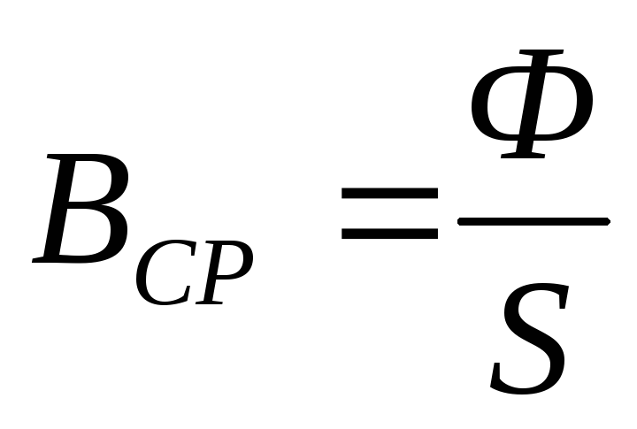
where Ф is the magnetic flux of one pole, and S is the area penetrated by this flux, then


here p is the number of pairs of poles (p = 1,2, ...).
The speed V can be expressed in terms of the armature speed n:
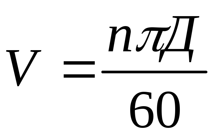
Substituting the resulting expressions into the formula for E i:

then we finally get:
E i \u003d C E F n.
It can be seen that the EMF of the armature is proportional to the frequency of rotation of the armature and the magnetic flux of the poles. Using Ampere's law, we find the force with which the excitation field acts on one armature conductor:
F = V cf l i I sin
,
here = 90 , I - current in the conductor.
This force creates a torque:
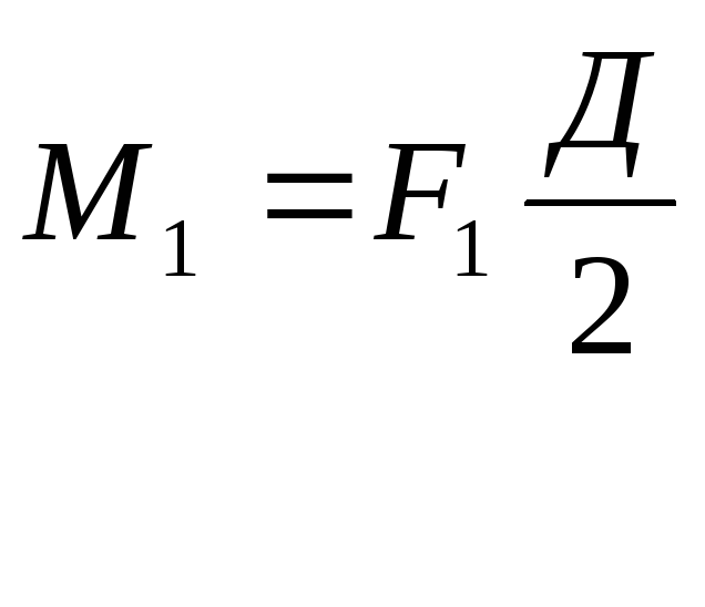
where D is the armature diameter. Multiplying by the total number of conductors N, we get the total moment:
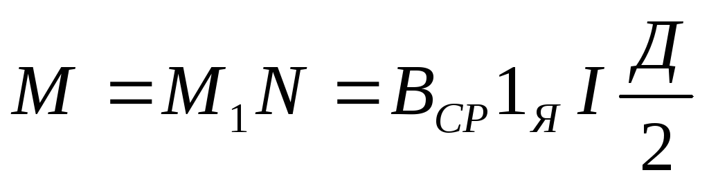
The average induction In cf, as before, we obtain by dividing the magnetic flux of one pole by the area permeated by this flux:
Since the armature current spreads along parallel branches, the current in one conductor is determined by the expression:

Substituting the expressions for B cf and I into the formula for the general moment, we get:
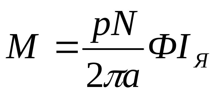
If we introduce a constructive coefficient
then finally we can write:
As you can see, the electromagnetic moment of the DC machine is proportional to the magnetic flux of the poles and the armature current.

The armature EMF formula Ea obtained above gives some average value of the EMF. In fact, its value fluctuates (pulses) between two limiting values - E min and E max. When the armature rotates, part of the turns, being short-circuited by the brushes, is switched off from the parallel branches, and during the time the armature is rotated through an angle corresponding to one collector plate, the sum of the instantaneous EMF values has time to change somewhat. The maximum value of the resulting EMF pulsations E = 0.5 (E max -E min) depends on the number of collector plates. For example, with an increase in this number from 8 to 40, the value of E decreases from 4V to 0.16V.
4. Armature reaction in DC machines.
When a DC machine is idling, the magnetic field is created only by the pole windings. The appearance of current in the armature conductors under load is accompanied by the appearance of a magnetic field of the armature. Since the direction of currents in the conductors between the brushes is unchanged, the field of the rotating armature is fixed relative to the brushes and excitation poles.
The armature winding becomes analogous to a solenoid whose axis coincides with the line of brushes, therefore, when the brushes are installed on geometric neutrals, the armature flow is transverse to the excitation flow, and its effect on the latter is called the transverse armature reaction. Having built the vector of the resulting flow, we see that it now rotates about the geometric axis of the main poles. The field of the machine becomes asymmetrical, the physical neutrals rotate relative to the geometric ones. In the generator, they are displaced in the direction of rotation of the armature, in the engine - against the direction of rotation of the armature.
Under the physical neutral we will understand the line passing through the center of the armature and the conductor of the armature winding, in which the EMF induced by the resulting magnetic flux is zero. The lateral reaction of the armature has little effect on the performance of the machine, this effect is usually not taken into account. However, when the brushes are displaced from the geometric neutral, a longitudinal component appears in the armature flux, its effect on the pole flux is called the longitudinal armature reaction. It can be both magnetizing and demagnetizing in nature. In general, the armature reaction leads to a distortion of the field under the poles and a change in the flux of the poles. The former can cause a significant increase in sparking under the brushes (up to the appearance of an all-round fire on the collector), and the latter in the generator changes the voltage at the terminals, and in the engine the torque and armature speed.
To weaken the armature reaction, the air gap between the stator and the armature is increased, special short-circuited turns are used in the grooves of the pole pieces. In machines of high power, a special compensation winding is used for this purpose. It fits into the grooves of the pole pieces, and is connected in series to the armature circuit, its flow balances the longitudinal flow of the armature.