Universal digital meters, otherwise referred to as multimeters, have become indispensable helpers for many radio amateurs and electricians. Despite the abundance of modes, it is really easy to work with them, and today we offer the most complete instructions on the use of these devices.
Inspection of the body and controls
The vast majority of digital multimeters have a similar appearance and layout of controls and indications. It is worth noting that the ergonomics used turned out to be very successful and comfortable to use.
The main switch is located in the center - a disk with a longitudinal handle, which simultaneously serves as a position indicator with the desired mode. The modes and measurement ranges themselves are printed in the form of inscriptions in a circle from the switch. For convenience, adjacent modes are combined into groups (the inscriptions are framed), inside each one you can switch between the measurement limits.

Please note that the switch itself can be through, that is, there are identical inscriptions on both sides of the pointer. In other words, only half of the turnover is available for selection. Typically, such a circuit is used on current clamps, while multimeters for the most part have a full 360º to select the desired mode.
In addition, the multimeter has an LCD display. Additional buttons may be located around it, including the backlight of the display and some additional functions. One or more additional buttons of the device can be located on the side faces of the device.

In the lower part of the case there are several holes with connectors for connecting probes. The connector labeled COM is the common negative contact for connecting the black probe. The remaining connectors (usually two) are used to connect the red probe: one for a wide range of measurements and one additional (signed A or ADC) for high current measurements.
Voltage measurement
The easiest way to measure voltage is with a multimeter. Two groups of measurements are intended for this: DCV for direct and pulsating current and ACV for alternating current. In the latter mode, the polarity of the probes can be omitted, because the alternating current does not have polarity as such.

The measurement limits for all multimeters are different, usually DC measures up to 1000 volts, and AC up to 700 or 750 volts. At the same time, there are several measurement ranges and, for example, when trying to measure a higher voltage within the limit of up to 20 V, the device will simply give incorrect readings. But it’s definitely not worth measuring the voltage obviously above the maximum limit, the device will simply fail. For some models, exceeding 100-200 V does not lead to death, but still it’s not worth the risk.
When measuring direct and pulsating current, polarity must be observed. This is a kind of opportunity to determine the polarity of an unknown source: if the probes are mixed up, then a minus sign will appear in front of the voltage value. Just in case, we recall that the voltage is measured with the device connected in parallel.
How to use the built-in ohmmeter
In a multimeter, the resistance measurement function is considered the most popular. Typically, the range group of the built-in ohmmeter is at the bottom of the mode circle, marked with the symbol Ω (Omega) and divided into ranges from 100 or 200 ohms to several hundred kilohms. Sometimes it is even possible to measure up to 10-20 MΩ through a separate connector for connecting a positive probe (External Unit) and with a connection external source nutrition.
When choosing different limits, the device continues to give correct readings, only the position of the separator point changes and, accordingly, the number of decimal places. However, if the measurement limit is much less than the measured resistance, then the device will not give any readings at all.

If the resistance of the measured resistor is unknown, it is better to move from the lower limit to the highest one. The resistance measurement accuracy of most multimeters is low, about 1-2%. With a natural resistor tolerance of 5-10%, the deviation from the declared value can be very significant. And the higher the range of measured values, the greater the error, especially for the megohmmeter mode.
When measuring resistance, two more facts must be taken into account. Firstly, with a discharged battery, the accuracy of the readings can be extremely low. Secondly, if you measure very low resistances (units and tens of ohms), take into account the own resistance of the device and probes, which is determined when the probes are short-circuited. Also, when measuring resistances, the most accurate value is indicated after 3-5 seconds, and not immediately.
We measure the current in the circuit
To measure the current, the device must be connected in series with the load circuit. The main connector for measurements is limited to rather small values - 0.2-0.5 A. Through the high-current connector, you can measure up to 10 A, but at the same time, the allowable voltage in the network is reduced by 30-50% of the maximum measurement limit of the device. To measure the current, the switch must be set to one of the positions of the DCA (constant) or ACA (variable) group. The last type of measurement is found only in expensive devices.
Please note that in order to measure the strength of an alternating and direct current different groups of ranges are provided. It’s not scary to confuse them, it’s just that the device will not show the correct values. Exceeding the maximum allowable current on a low-current connector leads to a blown fuse or failure of the device; on a high-current connector, to a blown fusible link.
Please note that in cheap Chinese multimeters, two positive connectors can be short-circuited and, of course, it will not work to measure high currents with them. Otherwise, everything is simple: choose the desired range, but it is better to move from the largest to the smallest. The device allows you to measure even microamps, but the measurement accuracy of most digital devices is traditionally lame.
Continuity of the circuit and diodes
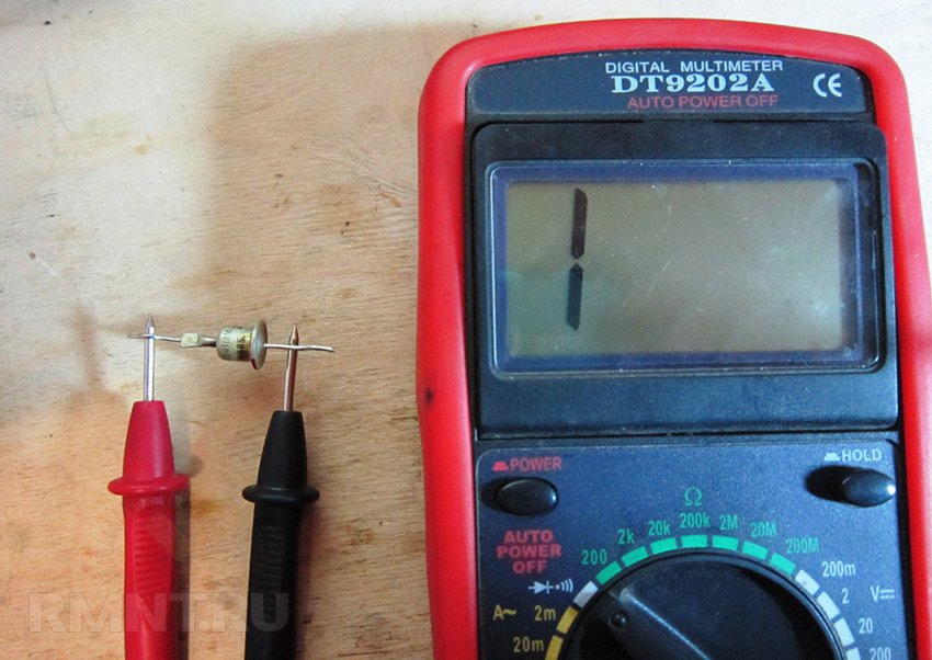
The diode symbol mode is designed to determine the voltage drop in a closed circuit. To test a diode, you need to touch its different leads, and then swap the probes. In one of the positions, some readings will be displayed on the display, in the other, the multimeter will not react in any way.
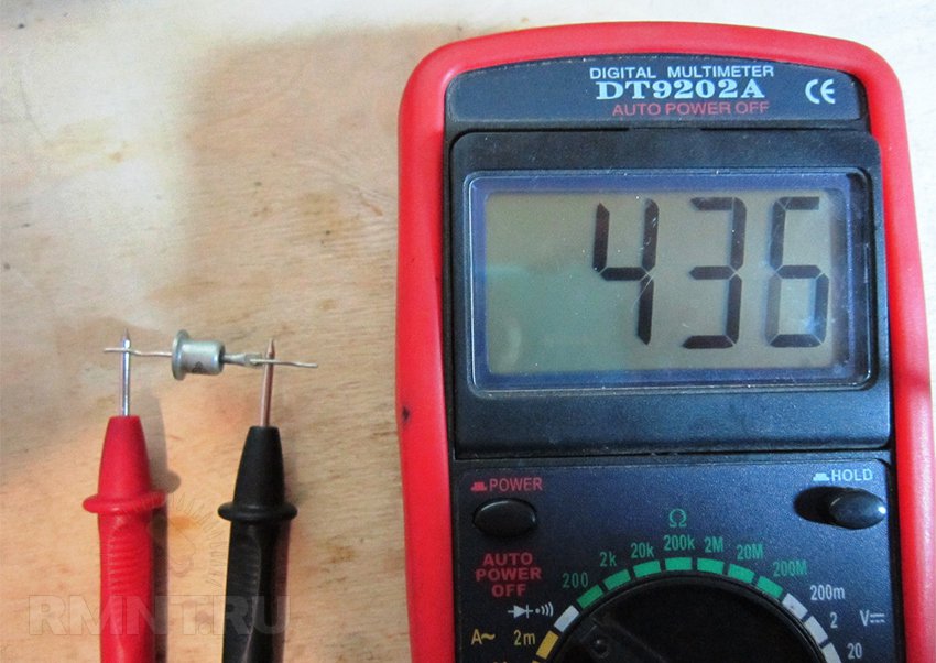
By the presence of readings, one can judge the polarity of the diode; in this position, the black probe points to the cathode. In fact, in this mode, the multimeter becomes a current source of 1 mA, and the readings on the display are nothing more than a voltage drop in mV. Diodes can also be called in ohmmeter mode: current will flow in one direction, but not in the other. However, it is the voltage drop that allows you to determine the characteristics of diodes without marking.
The sound continuity of the circuit in most models of multimeters is the smallest measurement range of an ohmmeter. If the resistance is below a certain threshold, which is usually 100 ohms, the piezo emitter built into the device will turn on. Sometimes the sound appears with a noticeable delay.
Temperature measurement
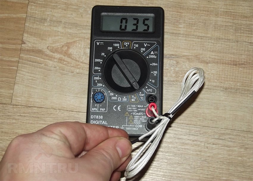
Some multimeters are equipped with a thermocouple, thanks to which you can measure temperatures, including very high ones - up to 700-800 ºС. The thermocouple has a double plug and is installed in the COM connector and adjacent to it, or in a special pair of connectors marked with the letter "C".

In the latter case, among the multimeter modes there is a similarly marked switch position. In it, the display will show the value in degrees Celsius. If the multimeter does not have special connectors and mode, you can measure the temperature in DCV mode at the smallest limit. In this case, you need to use a table or a graph of the dependence of thermo-emf on temperature.
The measurement accuracy in the latter case will not be very high: the voltage conversion will show not the actual temperature at the end of the thermocouple, but the difference between the object being measured and the temperature of the multimeter itself. Compensation for this phenomenon is present in most devices with a special mode and connectors.
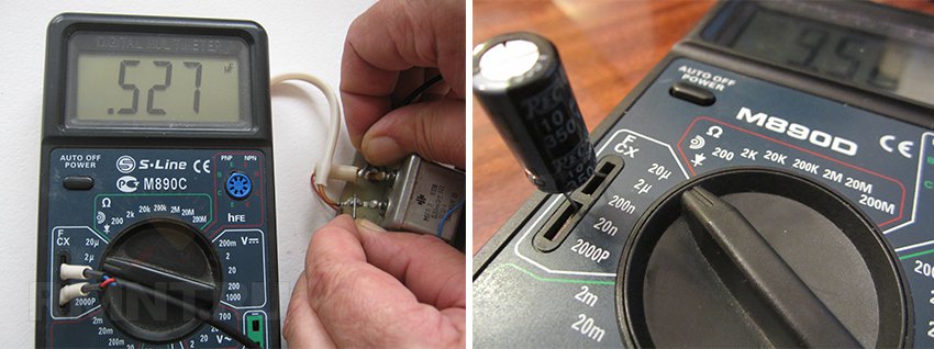
Checking field and bipolar transistors
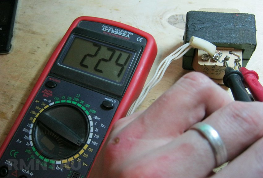
Even the simplest multimeters are able to test transistors and determine their pinout. For bipolar transistors hFE mode and a special terminal block are provided. The block is divided into two groups for P-N-P and N-P-N structures. Each contact is marked with the letters B (base), C (collector) and E (emitter).
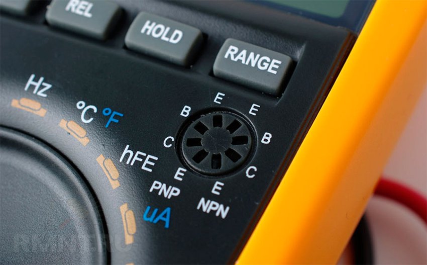
The contacts are located in such a way that a three-terminal element with an unknown pinout can be quickly rearranged by turning it in different directions, and at the same time all combinations were tested. When the desired pinout is found, the display of the device will show readings - the transfer coefficient of the transistor.

Please note that the contacts of the block are hidden deep enough and therefore transistors with short legs, most likely, will not be able to be tested. Also, it will not be possible to check high-power transistors in this way: the current generated by the multimeter to open the transition is limited to a few microamps.
Field-effect transistors are checked in the diode continuity mode and the pinout must be reliably known. First, the negative probe is applied to the drain, positive to the source. This checks the serviceability of the internal diode, when the reverse connection is made, there will be no voltage drop.

If, without removing the negative probe from the drain, touch the positive gate, the transistor will open, and the voltage drop between the drain and the source will become smaller and appear in both directions. You can close the transistor by touching the gate with a black probe without removing the red one from the source. For P-channel transistors, the verification algorithm is similar, but at each stage, the probes are swapped.
Special keys and functions
In conclusion, let's talk about special functions, which are present in many multimeters, the cost of which exceeds 1300 rubles. The most important and frequently used is the HOLD key, which allows you to fix the current position on the display. One funny situation is connected with this: if the HOLD key is pressed, then when turned on, the multimeter will show anything on the display that can be regarded as a malfunction.
Also in the display area of advanced devices there are keys by pressing which you can force the device to display only the maximum, minimum or average readings instead of the actual ones. When you turn on various additional modes, the corresponding mnemonic symbol is shown on the display.
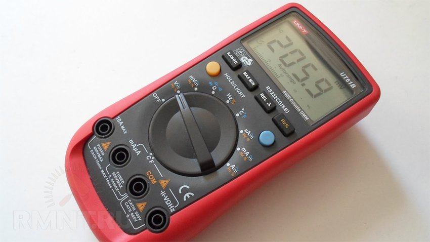
In the most advanced models, there are also functions for measuring the capacitance and frequency of the input signal, some multimeters even have a built-in oscilloscope and inductance measurement mode. Also, for expensive multimeters, there is no choice of the measurement limit on the circular switch. Instead, the mode is selected, and the limit itself is switched by the +/- buttons in the display area.
Multimeter Basics - practical guide for beginner electronics
A multimeter is the main device of a radio amateur, a great helper for any electronics engineer. Therefore, we will get to know this device better and learn how to work with it.
In amateur radio creativity, it is often necessary to measure voltage, current, and resistance. Previously, for this it was necessary to purchase or even design several different devices on your own: a voltmeter, an ammeter, an ohmmeter. But now there is no need for this: the multimeter is a universal device, and can be used to measure all the main parameters of simple home-made structures.
On sale you can find a huge range of different models of multimeters - from simple and inexpensive to professional, multifunctional, with increased accuracy and an impressive price.
Here we will consider working with the simplest and cheapest device that can be purchased at radio shops, radio markets, hypermarkets such as Leroy Merlin, Ob, etc. A similar device is included in the set of young electronics engineer NR02.
Devices of this class may have a slightly different design, different modes of operation, but in general, work with any similar multimeter will be similar.
The reliability and measurement accuracy of this device, of course, do not shake the imagination, but as the first device of a young electronics engineer, this multimeter is a good option.
If the passion for electronics develops into a hobby, you can always buy a more serious device: multifunctional, reliable, with increased accuracy.
Turning the device on/off. Battery Replacement.
The device is turned on by turning the mode switch knob to any position other than “OFF”. To turn off the multimeter, turn the mode switch knob to the “OFF” position.
Some models have an auto power off function: if the device is not used for more than 10 minutes, it will automatically turn off, which allows you to save battery life. By the way, about the battery: the multimeter is powered by a Krona battery. With occasional use of the device, the battery life should last at least a year. If the numbers on the display lose their contrast, or the device stops turning on at all, the battery should be replaced. To do this, remove the back cover of the device, remove the old battery and insert a new one.
Now consider the operation of the device and the most basic measurement modes.
DC voltage measurement (voltmeter mode)
Let's measure the voltage of a standard AAA battery. Her Rated voltage- about 1.5V. But suppose we don't know this.
Set the switch to the "1000V" position and touch the battery terminals with the probes. The indicator shows "001". Therefore, the battery voltage is about 1V, but in this mode it is measured very roughly - we lack such accuracy.
We translate the mode switch to position "20" and repeat the measurement.
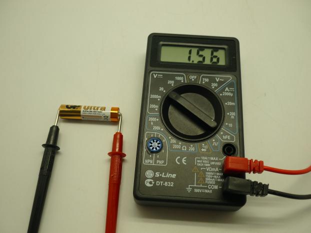
In this mode, the voltage is measured with greater accuracy, and from the readings on the display of the device, we see that the battery voltage is 1.56V.
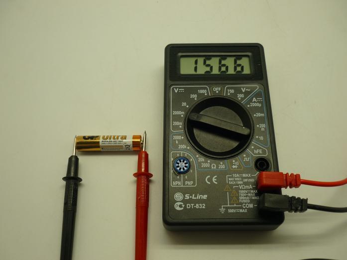
Let's move the mode switch to the "2000m" position, which corresponds to the maximum measured voltage of 2000 mV (or 2V). Let's repeat the measurements and get an even more accurate result - 1566 mV or 1.566V. Perhaps such accuracy is even redundant.
And now let's move the mode switch to the "200m" position. The maximum voltage that can be measured in this mode is 0.2V. We will apply almost 8 times higher voltage to the probes of the device - 1.5V. In general, doing this is not very correct - you can ruin the device. As a rule, the multimeter's built-in protection is able to cope with such "abuses", although it is often not recommended to check this.
We touch the battery terminals with the probes and see the symbol “1” on the display - an overload indicator. This is quite natural - after all, the measured voltage is much higher than the limit for this range of 0.2V.

So, let's remember the main rule: when measuring an unknown voltage, be sure to set the operating mode switch to the highest subrange (in this case, 1000V). Then, having understood the approximate value of the measured voltage, you can move the mode switch to the optimal position.
The device has built-in overload protection. For example, if you apply a voltage of 2V to the probes of the device, which is switched on in the “200m” mode, nothing bad will happen: the device will simply show the overload symbol “1” on the display. But if you apply a voltage of 200 V to the probes of the device included in this measurement subrange, it may fail.
In addition, when measuring voltages above 40V, you do not need to touch bare wires with your hands - this can be life threatening!
There is one more subtlety. In all previous experiments, we observed the polarity of voltage measurement: the red probe of the device was connected to the “+” terminal of the battery, and the black probe was connected to the “-” terminal. But if you mix up the probes, nothing bad will happen, the device will correctly measure the voltage - this is the normal mode of operation. Only the display will show a “-” sign, indicating that the polarity of the probes connected to the voltage source is incorrect.
Resistance measurement (ohmmeter mode)
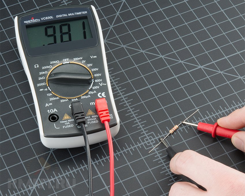
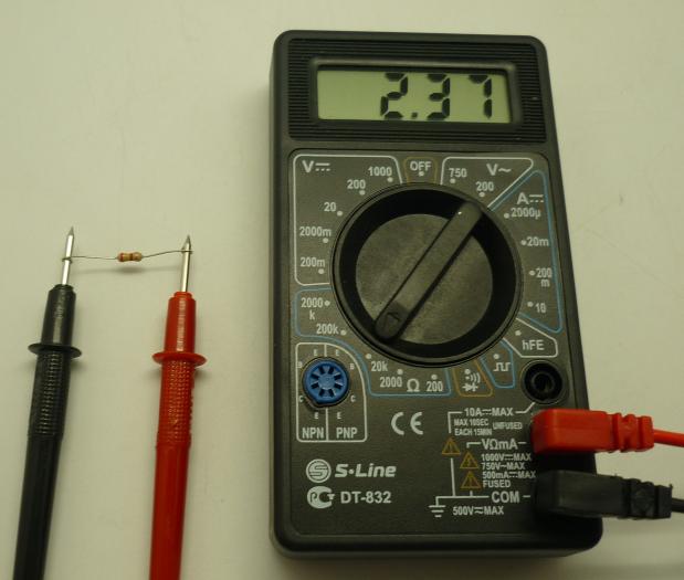
We connect a resistor of unknown value to the probes of the device. Using the mode switch knob, we set the most optimal measurement range - for this resistor this is the “20k” range. The display shows the measured resistance - 2.37 kOhm.
If we measure the same resistance in the position of the mode switch knob “2000k”, we will see the readings “002” on the display and conclude that the resistance of the resistor is about 2 kOhm. But such accuracy does not suit us at all - we need to choose a more optimal measurement range.
If we take a measurement in the “2000” (2000 Ohm or 2 kOhm) position of the mode switch knob, we will see the symbol “1” on the display, indicating that the measured resistance is above the measurement limit.
Thus, when measuring resistance, the main thing is to choose the optimal measurement range. True, unlike voltage measurement, when operating in the “ohmmeter” mode, an error in choosing a range cannot disable the device.
Let's try to determine the value of the resistor in an alternative way - by its color code. Color stripes are applied to the body of the resistor: red, yellow, red, golden. From the reference tables we find that the nominal resistance of this resistor is 2.4 kOhm, and the accuracy is 5%. This means that the actual resistance of the resistor can lie in the range of 2.28 ... 2.52 kOhm, which is quite consistent with the value obtained as a result of our measurements.
Measurement of current strength (mode "ammeter").
Current is always measured at an open circuit. For example, it is completely unacceptable to measure current by connecting the probes of the device directly to a voltage source (for example, a battery).
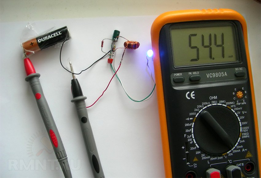
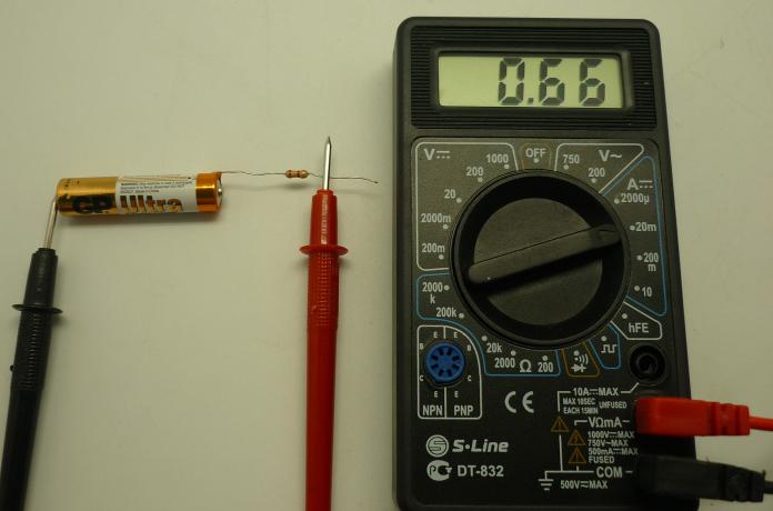
Let's collect the simplest chain battery and resistor. Let's measure the current in this circuit: 0.66 mA. As always when working with a multimeter, the main thing is to choose the correct measuring range.
As in the case of voltage measurement, you need to start measuring the current strength from the largest subrange - in this case "200m" - 200 mA. (This device can measure current up to 10A, for which you need to switch the red terminal of the probe to the highest socket of the device. But a beginner electronics engineer will most likely not have to work with such high currents, so this mode is not described in detail here).
It is important to remember this: by turning on the device to the current measurement range, for example, by 2000 μA (2 mA) and letting a current of several hundred milliamps through the device, you can damage the device. In some cases, the fuse built into the device blows, and you can easily get off by replacing it. But other components of the device often fail, and its repair becomes difficult and irrational.
Now let's try to calculate the current strength in this circuit theoretically. From previous experiments, we know the voltage of the battery (1.566V) and the resistance of the resistor (2370 ohms). According to Ohm's law: Current = Voltage/Resistance = 1.566/2370 = 0.66 mA.
Everything is like in a pharmacy: Ohm's law works, and so does our device.
So, we met with a multimeter, a faithful assistant to every radio amateur. Measuring DC voltage, resistance and current strength is 95% of the modes that a beginner electronics engineer needs.
Working with the device in other modes (measurement AC voltage, frequency, parameters of transistors and diodes) will be considered separately.
Word multimeter consists of two words: multi - many and meter - measurements, measuring device. These definitions can be found in English-Russian dictionary multitran, and therefore, with full confidence we can say that a multimeter is a lot of measuring instruments "packed" in one small box. All these measuring instruments are designed for measurements in electrical circuits, and to start a story about electrical measurements, without remembering Ohm's law, it would be unforgivable.
In school textbooks about Ohm's law for a circuit section, it is written like this: "The current in the circuit (I) is directly proportional to the voltage (U), and inversely proportional to the resistance (R)". Everyone who deals with electricity seriously knows this phrase as Our Father. And then to say, not knowing Ohm's law - stay at home.
If Ohm's law is written as mathematical formula, then it turns out quite simply: I \u003d U / R.
This is Ohm's law for the chain section, which we will restrict ourselves to here. To obtain correct results, you should substitute the values \u200b\u200bof current in Amperes, voltage in Volts, resistance in Ohms into the formula. The first letters are capitalized, since the units of measurement are derived from the names of the scientists who discovered these laws.
True, it is not forbidden to substitute, for example, resistance in kiloohms (1 KΩ \u003d 1000 Ohms), then the current will turn out in milliamps (1 mA \u003d 0.001 A). Such a substitution in low-current circuits has to be used quite often.
The simplest electrical circuit, shown in Figure 1, consists of a voltage source, connecting wires, a switch, and a load. But using this circuit as an example, you can see everything that is mentioned in Ohm's law, everything that can be measured using instruments, get acquainted with the connection of an ammeter, voltmeter and ohmmeter.

Figure 1. The simplest electrical circuit
Lots of instruments for simple measurements
The electrical circuit shown in Figure 2 is powered by a DC source - a galvanic battery, so the ammeter and voltmeter must be designed to measure in DC circuits. If even such a simple circuit is powered by alternating current (220V, switch, light bulb), then the devices will be required alternating current. It turns out that you will need a whole bunch of devices, even with such a simple scheme!
This simple circuit shown to brush up on how to connect appliances. You can read more about measuring currents and voltages in the article.
It is very easy to get rid of such a number of devices: to collect all the devices in one case and, using switches, connect the same measuring pointer head to each of them. Such devices were once called combined or avometers - Ampere Volt Ohmmeter.
Another name for these devices is a tester, from the English test - verification, test, since the accuracy of measurements by such devices is low. As a rule, these are devices of the 4th accuracy class, i.e. the measurement error is 4%, which is quite sufficient for most practical purposes.
At present, pointer testers, not only have retired, but are used quite rarely, although in some cases, they simply cannot be dispensed with. But many, mostly old specialists, prefer to use pointer avometers. Well, it's who's used to what. So, slowly, we approached the modern combined instrument - the multimeter.
Modern digital multimeter
Unlike antique avometers - testers, the multimeter has become a digital device, on the packaging box it says "Digital multimeter". This is not because the readings are displayed in the form of numbers, the difference lies in the very principle of operation. The measured value, voltage, current or resistance is converted into a digital code using an analog-to-digital converter (ADC), which is then displayed on a digital liquid crystal display.
In addition to the actual measurement results, the indicator can show additional information: the state of charge of the battery (when it is time to change the battery, a blinking image of the battery appears on the display) and a warning about measuring high voltages. Multimeters, with small dimensions and low price, have high measurement accuracy, which ensured their well-deserved popularity among users.
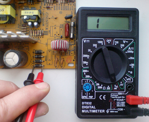
The easiest way to deal with the device and the operation of the device is when it is in the hands. But, as long as there is no such possibility, then a picture with the image of the device is quite suitable. It is enough to take a photo and provide it with explanatory inscriptions. A similar photograph is shown in Figure 3 (click on picture to enlarge).

Figure 3. D838 Digital Multimeter Appearance
Why and who needs a multimeter
Multimeters of the D83X series are a budget option - at a minimum cost, there is a set of all, or almost all, operating modes used by most electricians, electronics engineers and just those who have to deal with electricity from time to time. There are, of course, more expensive models that have additional measurement limits and various operational conveniences.
First of all, it is the ability to measure the capacitance of capacitors and the inductance of coils. Some multimeters even have a frequency measurement mode, although it is usually limited to frequencies in the audio range, up to 20 kHz. Almost all multimeters, including the budget version, have a mode for measuring the gain of low-power transistors, but they do not use it very often.
Additional options include the backlight of the scale (but how else to take measurements at night?) And the button to save the last measurement result. Such memorization makes it possible to record the result in a notebook or in a pre-printed table. Actually, a very useful feature.
The DT838 multimeter shown in Figure 3, as a nice addition, has a temperature measurement mode: if you simply turn the multimeter into this mode, then using the internal temperature sensor, you can monitor the temperature in the working room.
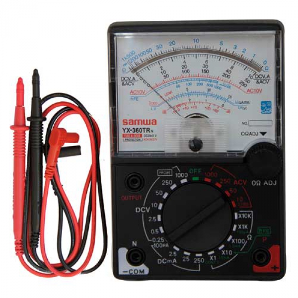
In the digital age, the pointer multimeter is still in demand.
The older generation of radio amateurs still have "tseshki", reliable Soviet devices. They faithfully serve their masters for several decades. And the new generation look at them as antiques and have no idea how to use a pointer multimeter without instructions. However, they have a number of properties that allow them to be in demand at the present time.
Purpose
A pointer tester is an analog device consisting of a pointer microammeter, a set of resistors and shunts. Another name for it is an avometer (ampere + volt). Initially, multimeters performed only three functions, they measured voltage, current and resistance. Then the feature set was expanded. When measuring voltage, high-value resistors are connected in series to the microammeter; to determine the current, a shunt, a resistor with low resistance, is connected in parallel to it.
When measuring AC current and voltage, diodes are additionally connected to rectify the input signal. Additional resistors and shunts have a high nominal accuracy, since the error of the pointer multimeter depends on this. The classic Soviet pointer tester is the Ts4352 model. It has a wide range of voltage measurement (up to 1200V), current (up to 15A) and resistance (up to 5MΩ). Moreover, this multimeter can measure the characteristics of both direct and alternating current. Today, its modifications are being released, which are in demand.
Design features
The main element of the pointer multimeter is the magnetoelectric measuring mechanism in the microammeter. The main characteristics of the multimeter depend on its sensitivity.
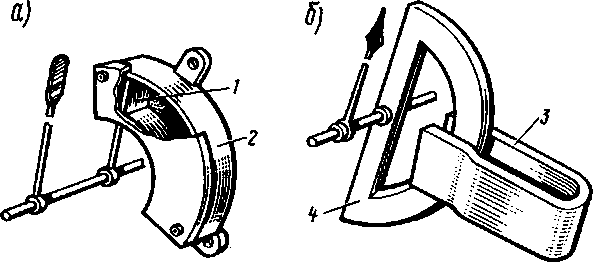
Structurally, it consists of two permanent magnets with pole pieces. Between tips with identical poles there is a cylindrical gap in which a steel core is located. In fact, it floats in a magnetic field without touching any magnet. An aluminum frame is placed in this gap, enclosing the core along its length. The winding is wound around the frame with a very thin wire. It is attached to the axis, which is connected by braces or coil springs with an arrow. The current measured by the switch tester is supplied to the coil through them.
When current passes through the winding, all turns of it will experience the action of electromagnetic force. The total effect of all forces will create a torque that will turn the coil and with it the arrow. At permanent magnet its field induction is also constant, and the number of turns of the winding, its size and the air gap for a particular mechanism are known. Therefore, the torque (deflection force) of the arrow will depend only on the strength of the current flowing through the coil. The angle of deflection of the multimeter needle will depend on the stiffness of the coil springs. The torque must be balanced by the counter moment of the coil springs, while the arrow will freeze. The deflection angle will depend on the strength of the current. Therefore, pointer testers with a magnetoelectric mechanism have a linear scale.
Stable readings
In order for the arrow not to dangle, but to quickly calm down, air and magnetic-induction dampers are provided. The aluminum frame is such a damper, creating eddy currents when the coil turns and, according to Lenz's rule, the resulting braking force calms it in this way. To compensate for the influence of gravity, counterweights with a variable center of mass are provided.
To eliminate the influence of temperature, resistors with a small temperature coefficient of change in resistance are installed.
Since the direction of the deflection of the arrow depends on the direction of the current, the polarity of the measured signal must be taken into account during measurements. With the direct use of a magnetoelectric device, it will not be able to measure alternating current, since the total torque will be zero.
In order to still measure the alternating current with a dial multimeter, it is first rectified using diodes.
Advantages and disadvantages
Analog gauge in measuring mode constants has a linear scale - this is a plus. But when measuring resistance, you have to use a non-linear scale - this is a minus of the multimeter. Since the arrow of the device has a certain mass, it is inertial. And this property allows the multimeter to be an excellent integrator. It is very convenient for the perception of information. It smoothes small frequent fluctuations, which allows you to immediately evaluate the information provided. A digital multimeter, with the same input signal, produces flashing numbers, and the perception of the instrument readings is difficult.
The main advantages of a pointer multimeter:
- visibility;
- quality perception;
- the ability to evaluate the measured signal as a whole.
The inertia of the arrow allows the multimeter to be resistant to interference. In addition, it is convenient for them to monitor the change in current on a charging capacitor. When working, you do not need to constantly watch the multimeter, the movements of the arrow are perfectly fixed with peripheral vision.
At the same time, due to the limited sensitivity of the magnetoelectric mechanism of the device, it is not possible to use resistors with a very high rating. This introduces an additional error in voltage measurements. And when measuring the current, the tester cannot fix it at very low shunt ratings, when almost all the current will pass through it.
Compared to digital testers, pointer testers are more susceptible to mechanical stress due to the sensitive measuring head, depend on the state of power supplies, but are more economical.
Additional features
A pointer tester can measure the capacitance of capacitors, some models can measure temperature, determine the health of semiconductor elements. There are multimeters with a built-in test signal generator for several (up to ten) frequencies.
From a normal manufacturer, the package includes:
When buying, you need to pay attention to the compliance of the dial multimeter with the safety standard 89/336 / EEC.
The voltage test range is 500-1000 V, current up to 10 A. It is convenient to use a pointer tester to check wires and check grounding. Some have a sound or light alarm when a resistance of 20-30 ohms and below is reached, this is very convenient. With an average pointer multimeter, you can carry out almost all the measurements necessary in everyday life for an ordinary person. Their functionality is designed for just that.
Voltage and current measurement
Consider, for example, the m1015b pointer multimeter, which meets all safety standards. On the front side of the device there is a function switch, zero adjustment, an arrow with scales, sockets for connecting measuring probes.
To measure DC voltage, the function switch is set to DCV. Measuring probes are connected in parallel with the load on which the voltage will be measured. Readings are taken on the instrument's black V.mA scale. If the signal range is unknown, you need to choose the largest one, then switch to the optimal one for this signal.
When measuring AC voltage, the switch is moved to the ACV position. Everything else is done in the same way as when measuring DC voltage.
To measure the current, the rotary switch is set to DCmA, depending on the current range. Start measurements from the maximum scale. Readings are taken on a black scale.
Resistance and decibel measurement
When measuring resistance, the device or part under test must be disconnected from electricity. The mode switch is moved to the Ω position.
With a special button of the zero regulator, the arrow of the multimeter is combined with the zero division of the resistance measurement scale. Before this, the probes must be short-circuited. If you cannot set the arrow to zero, you need to replace the battery. To do this, the back cover is removed and replaced.
After that, the probes are connected to the measured resistance. The ohmmeter readings are taken on a green scale. The multiplication factor depends on the selected range.
To measure dB, the mode switch is set to the required position of the ACV dial multimeter.
For a range of 10 V AC, readings are taken on the red dB scale, for a range of 50 V, a correction of +14 must be entered in the range of -20 ... 22 dB, for 250 V, a correction of +28 for a range of 8 ... 50 dB. If the signal has a constant component, it is necessary to carry out measurements through a capacitor with a capacity of less than 0.1 μF.
Subject to the rules of use, the tester does not require any maintenance. It can work at positive temperatures up to 40 degrees and humidity of 75%.
When they mention a multimeter, they usually mean a compact, self-powered mobile device. But there are also stationary pointer testers. Their set of functions can be the same as that of portable ones or a little wider, and the accuracy of measurements, the number of ranges is necessarily higher.
Which device to choose, digital, pointer, stationary or mobile, depends on the needs of the consumer, but pointer multimeters will be in demand for a long time.