In car direct current the armature winding has low resistance and when connected to the network, starting currents occur, which can reach 15 ... 20I nom. An increase in armature currents above the value of 2...2.5I nom leads to a deterioration in switching.
In addition, the resulting dynamic forces can gradually destroy the armature winding, cause shearing of the keys, twisting of the shafts, etc. The limitation of starting currents is carried out with the help of resistances r 1, r 2, r 3, included in the anchor circuit (Fig. 2.12). As the motor accelerates, the EMF increases and the current decreases. By successively shorting the resistances with the contacts KM1, KM2, KMZ, they perform (perform) a start. The starting diagram of the engine is shown in fig. 2.13.
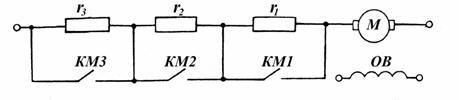
Rice. 2.13. Scheme for switching on starting resistors ..
The values of switching currents I 1 and I 2 are selected based on the requirements of the technology for the electric drive and the switching capacity of the motor. So, they take I 1 \u003d (2.0 ... 2.5) I H and I 2 \u003d (1.2 ... 1.3) I H in cases where the duration of the engine start affects the performance of a frequently turned on machine .
If you want to smooth start, for example, passenger elevators, then the values of the switching currents will be determined by the allowable accelerations of the electric drive. In cases where the start is rare and the start conditions are not limited, the values of the currents I 1 and I 2 can be taken slightly more than the operating currents (but much less than in the first case, when I 1 = (2 ... 2.5) I N.
Values starting resistances calculated by analytical and graphical methods. If the number of steps is set, this means that the calculation is carried out for an already known standard contactor panel. If the number of steps is not known, it is required to select
Analytical method for calculating starting resistances
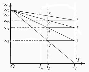
When the engine is connected to the network, acceleration begins with starting resistance R 3 \u003d r I + r 1 + r 2 + r 3 (Fig. 2.13). These resistances correspond to an artificial electrical mechanical characteristic
1 - 2 - ω 0 (Fig. 2.14). At current I 2 and speed ω 2 (point 2), additional resistance r 3 is shunted by KMZ contacts, and the motor current increases again to I 1 (point 3). The start continues with resistance R 3 \u003d r I + r 1 + r 2 according to the characteristic Z - 4 - ω o. At point 4 of this characteristic, r 2 is switched off by contact KM2. With resistance
R 3 \u003d r I + r 1 the engine accelerates according to the characteristic 5 - 6 - ω o. At speed ω 6 (point 6), the last resistance r 1 is turned off, and the motor enters the natural electromechanical characteristic 7 - 8 - ω o, along which it accelerates to a speed corresponding to the load on the shaft.
To determine the values of additional resistances, we take the ratio of currents corresponding to points 3 and 2 at the angular velocity ω 2 of the starting diagram:
![]() . (2.31)
. (2.31)
Rice. 2.14. Starting diagram DPT NV.
The motor EMF values at these points are equal, since the rotational speed ω 2 DOES NOT CHANGE
After reducing the voltage, we get:
![]() .
.
At the angular velocity ω 4 for points 4-5 we write:
![]() ;
;
here E 4 \u003d E 5, and the currents I 5 \u003d I 1, I 4 \u003d I 2, therefore:
![]() .
.
Similarly for the angular velocity ω 6 (points 6 and 7):
![]()
or ![]() .
.
Let us denote the ratio of switching currents: , then
If there were m steps, then by analogy:
In this expression, the number of starting stages m and the multiplicity of starting currents are interrelated:
![]() (2.34) or . (2.35)
(2.34) or . (2.35)
The resistance value of each stage can be determined as follows:
The procedure for calculating starting resistances
If the number of steps m is given, then the resistance calculation is performed as follows:
1) set the current value I 1 and determine R m:
2) find the ratio of switching currents:
![]() , (2.37)
, (2.37)
where ; P n, U n, I n, η n - passport data of the engine;
3) calculate the value of the second switching current I 2:
and compare it with the operating current of the motor I s, corresponding to the maximum torque of the working machine at start-up.
If the working moment M s is known, then
![]() ,
,
and if the power on the shaft of the working machine is given P V.r.m. , then
![]() .
.
For I 2 > (1.1...1.2) I c, we determine the resistance of each stage:
...![]() . (2.38)
. (2.38)
If the condition I 2 > 1,1I c is not met, then we choose a new
(greater) value of I 1 and repeat the calculation.
If the number of resistance steps is unknown, then the calculation is carried out in the following sequence:
1) we set the values of the switching currents I 1, I 2 and determine λ:
2) determine the number of steps:
where ; ![]() .
.
The resulting value of m (if it is fractional) is rounded up to
nearest integer and specify λ and current I 2:
![]() ; .
; .
Further calculation is carried out as in the first case. After completing the calculations for the first or second option, it is necessary to check the correctness of the calculations. To do this, we determine the total
resistance:
and compare with the original. The deviation in the calculations should be within the permissible error - 5 ... 7%.
Graphical method for calculating starting resistances
This method of calculation gives a visual representation of the values of additional resistances, but has significant disadvantage -
the accuracy of the calculations depends on the accuracy of building the starting diagram of the engine.
Electromechanical characteristics for a DC motor with an additional resistance R ext. included in the armature circuit. shown in fig. 2.15.
Fig.2.15. Electromechanical characteristics of DPT NV with the introduction of additional resistors in the armature circuit.
EMF equation for rated current and speed ω
(dot at):
We divide the last expression into sf n:
![]() . (2.39)
. (2.39)
From Fig.2.15 we have:
 (2.40)
Comparing expressions (2.39) and (2.40), we write:
therefore, for constant values of I n and sf n, the value of the segment ab is proportional to . If the characteristic passes through the point r , then everything applied U n is balanced by a fall in
resistance R n:
R n bears the name nominal resistance,![]() . Rated motor resistance - e then this is the resistance of the armature circuit, at which at the moment of switching on (at ω = 0) the rated current flows in the armature winding. The segment ag is proportional to R n. Thus, according to the value of the segment cut off by the characteristic on the rated current line, it is possible to calculate the resistance of the armature circuit. But for this you need to know the scale
. Rated motor resistance - e then this is the resistance of the armature circuit, at which at the moment of switching on (at ω = 0) the rated current flows in the armature winding. The segment ag is proportional to R n. Thus, according to the value of the segment cut off by the characteristic on the rated current line, it is possible to calculate the resistance of the armature circuit. But for this you need to know the scale
resistance:
where ; U n, I n, R n, - rated voltage, motor current and power.
The first way to determine the scale is more accurate, since
segment ag is greater than segment ab.
When calculating the starting resistance of a DC motor by a graphical method, two options are possible.
1. The number of starting stages m is set.
According to the passport data of the machine, we build a natural electromechanical characteristic using two points (ω o, M = 0) and (I n, ω n)
(Fig. 2.16). Set aside the values of the switching currents I 1 and I 2 .
Their values must be substantiated based on the technology requirements for the electric drive and the switching capacity of the motor. The limiting value of the current I 1 is taken equal to (2 ... 2.5) I n. Current I 2 \u003d (1.2 ... 1.3) I n. Through the points corresponding to the values of I 1 and I 2 on the axis of the currents, we draw two straight lines parallel to the axis of the frequency of rotation. We connect points 1 and ω o with a straight line that intersects at point 2 with current I 2 .
Further construction order from point 2 to 3, etc. visible from Fig. 2.16. As a result of the construction, it is necessary to get to the intersection point of the natural electromechanical characteristic and the switching current line I 1 (point 7). If the match did not work out or the number of feet is not equal to the specified one, then it is necessary to change the value of the current I 2 or I 1 and repeat the construction.

Rice. 2.16. Graphical method for calculating starting resistances
Thus, the process of starting the engine in several steps, shown in Fig. 2.16 is characterized by the fact that the motor current during start-up varies from . At the beginning of the start, then, as the engine accelerates, its EMF increases, as a result of which the current in the engine armature circuit begins to decrease, and hence the engine torque. When the current reaches, part of the starting rheostat is turned off so that the motor current reaches the value again, etc.
As the starting resistors are removed, the resistance of the armature circuit decreases, and, consequently, the value of the electromechanical constant also decreases, which leads to a decrease in the duration of the start at each subsequent stage.
DC motors can have independent, parallel, series or mixed excitation (Fig. 6.1).
Rice. 6.1. Independent DC motor circuits ( a),
parallel ( b), sequential ( in) and mixed ( G) excitation
(the upper part of the scheme "c" belongs to the scheme "a")
In a parallel excitation motor, the field winding is connected in parallel to the armature terminals. But the current flowing through this winding, unlike the armature current, does not depend on the load and is determined by the voltage applied to the armature and the total resistance of the excitation circuit. For this reason, a shunt-excited motor is also called an independent-excited motor.
Torque M DC motor and its EMF E are determined by the formulas
M= to F I I; E= kФω,
where k is the design coefficient of the engine;
Ф – magnetic flux, Wb;
I i - armature current, A.
ω is the angular velocity, rad/s.
Electromechanical equations ω = ƒ ( I i) and mechanical ω = ƒ ( M) of characteristics have the form
ω = U/(kF) – ( R i + R p) / (k F) I I;
ω = U/(kF) – ( R i + R p) / (to 2 F 2) M.
Angular speed of ideal idle (at I i = 0 or M = 0)
ω 0 = U/(kF).
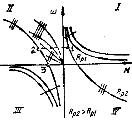
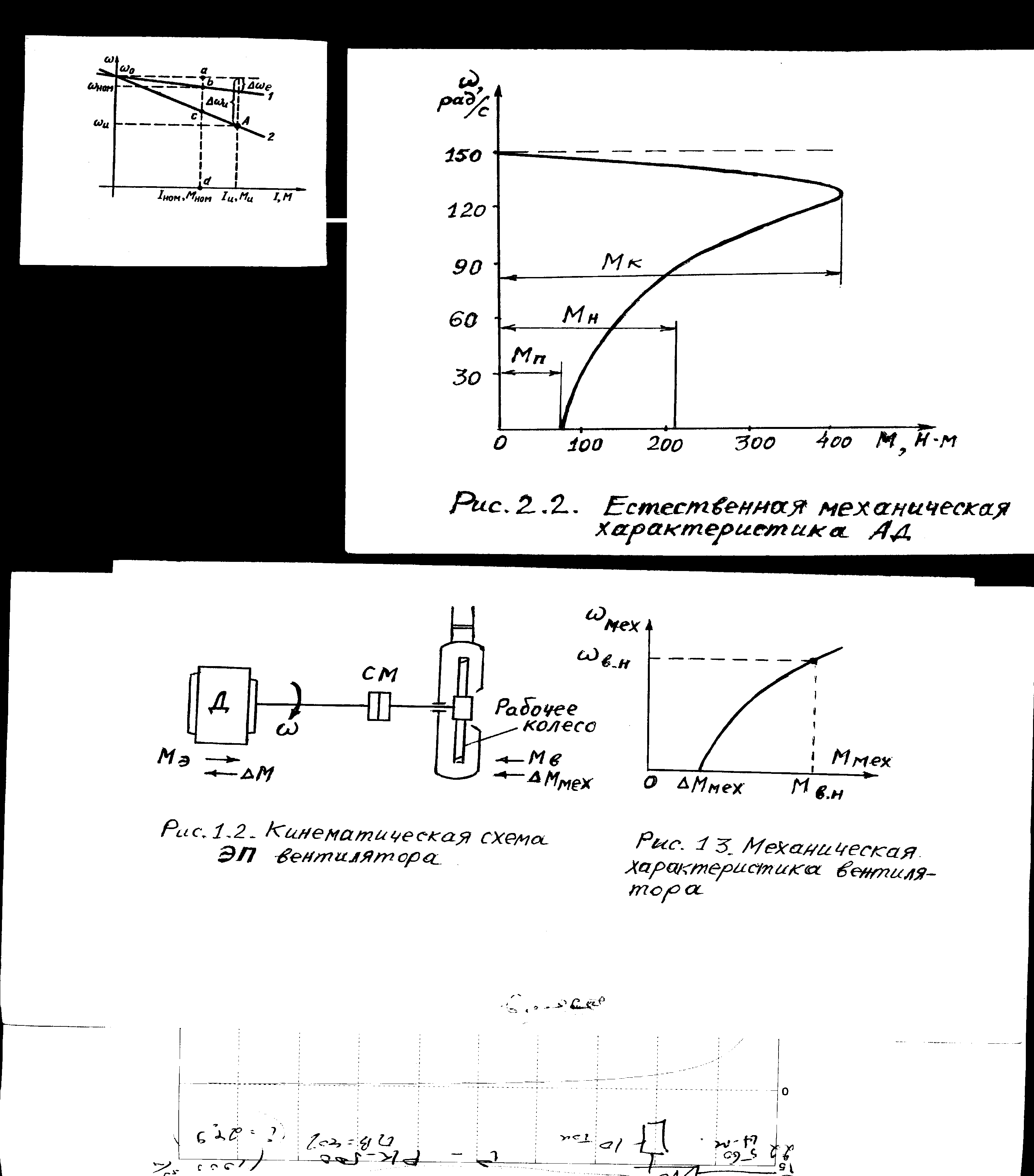
On fig. 6.2 presents the mechanical characteristics of a DC motor with independent excitation (DPT NV) in all operating modes. The characteristic points of the characteristics in the motor mode are: the point of ideal idle (ω 0, M= 0); nominal mode point (ω n, M n); dot short circuit (ω = 0, M = M to).
The rigidity of the mechanical characteristic is determined by the excitation flux and the resistance of the anchor circuit:
β = d M/dω = - to 2 Ф 2 / ( R i + R p) = - M to / ω.
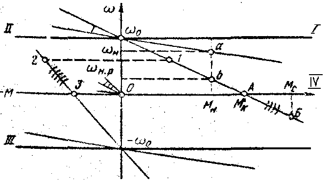
Rice. 6.2. Combined mechanical characteristics of a DC motor with independent excitation
The highest value of the stiffness modulus corresponds to the natural mechanical characteristic, since the excitation current is equal to the rated current and the control resistance R p \u003d 0. As the resistance of the rheostat increases R p the slope of the mechanical characteristic increases, and the angular velocity decreases. For a given resistance value R p and rated torque M n engine angular speed
ω n.r = ω 0 (1 – I n ( R i + R R) / U n.
To calculate the mechanical characteristics, it is necessary to know the armature resistance of the motor R i, which is specified in directories. In the absence of factory data, the value R I find approximately by the formula
R i \u003d 0.5 (1 - ŋ n) ( U n/ I n).
Since the mechanical characteristics of the DPT NV are straightforward, it is enough to have two points to plot them:
1) ω = ω 0 and M = 0,
2) ω = ω n (or ω = ω n.r) and M = M n.
For DPT NV, the following three modes of electric braking are possible.
1. Regenerative braking, which occurs when the engine speed is above ideal idle speed. It is the most economical, since the braking energy is transferred to the electrical network. The mechanical characteristics in this mode are a continuation of the corresponding characteristics of the motor mode in the II quadrant. The motor circuit does not change during regenerative braking.
2. Dynamic braking. The motor armature is disconnected from the network and shorted to resistance. In this case, the mechanical energy of the moving parts (mechanism and motor armature) is converted into electrical energy, which is lost in the form of thermal energy in the resistance of the anchor circuit. The mechanical characteristics in this braking mode pass through the origin (in Fig. 6.2 - lines with three notches).
3. Reverse braking carried out in two ways:
1) the introduction of high resistance in the armature circuit. In this case, the motor torque becomes less than the static load torque. M With. The engine stops (at point A), and then under the influence of torque M c starts to rotate in the other direction, developing a braking torque; at point B, the steady state occurs. Mechanical characteristics are a continuation of the corresponding characteristics of the motor mode (in Fig. 6.2 - lines with four serifs);
2) braking by switching the polarity of the armature winding along the way. Engine running at point 1 , after switching it will switch to the rheostatic characteristic at the point 2. Along the line 2–3 deceleration occurs (line with five serifs). At the point 3 the motor stops and must be disconnected from the mains to avoid switching to motoring mode with reverse rotation.
AT DC motor with series excitationde-niem the armature current is also the excitation current. The excitation magnetic flux increases with increasing load, as a result of which the angular velocity decreases according to equation (6.1) and the mechanical characteristic of the motor will be soft (Fig. 6.3). Thanks to this, the NV DPT overcomes overloads relatively easily and smoothly and has a high starting torque. These properties of the engine allow it to be widely used in the drive of transport mechanisms. The mechanical characteristics of the engine are significantly softened when a rheostat is introduced into the armature circuit (Fig. 6.3, lines with one notch).
Rice. 6.3. Mechanical characteristics of DC motor
with sequential excitation
In DPT PV, it is impossible to implement the regenerative braking mode, since there is no ideal idle speed in it.
Dynamic braking can be carried out according to the scheme with self-excitation and with independent excitation. In the first case, the armature and the excitation winding are disconnected from the network and closed to the rheostat. To avoid degaussing the machine, it is necessary to switch the excitation winding (or armature) so that the direction of the current in the excitation winding does not change. In this case, the machine is self-excited at a given resistance of the armature circuit only at a certain value of the angular velocity; excited, it creates a braking moment. Mechanical characteristics are non-linear (in Fig. 6.3 - curves with four notches).
The mechanical characteristics of the engine in the mode of dynamic braking with independent excitation are similar to the corresponding characteristics of the engine with independent excitation (in Fig. 6.3 - lines with two notches). This method of braking found wide application, and the first method is rarely used, mainly as an emergency, for example, when the mains voltage fails.
Braking by opposition is carried out, as in DPT NV, in two ways:
1) inclusion in the armature circuit of high resistance;
2) by changing the polarity of the armature winding, leaving the direction of the current in the excitation winding unchanged.
With the first method, the mechanical characteristic will be a continuation of the characteristic corresponding to the motor mode (in Fig. 6.3 - a line with three notches). In the second method, braking is carried out along the line 1 –2–3 .
Speed control of direct current electric drives. The speed of the DPT NV can be adjusted:
1) by changing the resistance in the armature circuit;
2) change in the flow of excitation;
3) by changing the voltage supplied to the armature.
Regulation according to the first method has significant disadvantages:
- the rigidity of the mechanical characteristics decreases with a decrease in the angular velocity, and the power losses in the main circuit increase;
- the control range is limited, especially at low loads;
– small smoothness and accuracy of regulation.
For these reasons, this type of regulation is rarely used in a DC drive.
By second way it is possible to regulate the magnetic flux only in the direction of decrease (since in the nominal mode the magnetic circuit of the motor is saturated), which corresponds to an increase in speed above the nominal one. The possible speed control range does not exceed 2 for a standard motor. The upper speed limit is limited by the mechanical strength of the engine armature elements - armature winding bandages, collector.
The main way to control the speed of DPT NV is a method based on changing the voltage supplied to the armature, which is carried out using a special adjustable converter. Thyristor converters are mainly used as individual power sources. The rigidity of the mechanical characteristics of the drive according to the system "converter - DCT NV" is almost constant. Mechanical characteristics are a family of straight lines parallel to each other. The range, smoothness, and accuracy of regulation are higher here than with other methods of regulation. Therefore, this drive system is used for mechanisms that require deep and smooth speed control.
Calculation of additional resistors in the DPT NV armature circuit. If the natural electromechanical or mechanical characteristic is known 1 engine (Fig. 6.4) and its passport data, then the calculation of the resistance R d, when included in the armature circuit, the desired artificial characteristic 2 will pass through point A with given coordinates ω and, I and or ω and, M and, can be performed by the following most common methods.
Rice. 6.4. Characteristics of DPT HB for calculating the value
control resistors
Proportion method. Let us write the ratio of the speed drops at the current I and or moment M and on the natural Δω e and the desired artificial Δω and characteristics:
Δω e / Δω u = I and R I / ( I and ( R i + R e)) = R I / ( R i + R e).
Then the desired value
R d = R i (Δω and / Δω e - 1).
Segment method does not require knowledge of the value of the internal resistance of the motor R i (moreover, its value can be determined by a known natural characteristic).
Let's write an expression for the motor speed on a given artificial characteristic (see Fig. 6.4) at rated current I n, moment M n, magnetic flux F n and voltage U n:
ω and = U n / (kF n) (1 - I n R/ U n),
where U n / (kF n) \u003d ω 0.
ω and = ω 0 (1 – R / R n).
Here R n = U n/ I n - the so-called nominal resistance, which is the base value in the calculations, Ohm.
Ratio
R / U n \u003d (ω 0 - ω and) / ω 0 \u003d δ
reflects an important property of the NV DPT: the relative speed difference δ \u003d Δω / ω 0 is equal to the relative active resistance of the armature circuit R / R n.
Let's designate in fig. 6.4 characteristic points a, b,With, d and note that ω 0 – ω and = Δω = ace, ω 0 = ad. Then R = R n Δω / ω 0 = R n ace/ad; R d = R n bWith/ad; R i = R n ab /ad.
Thus, to find R d you must first determine the length of the segments according to the characteristics bWith and ad at rated current or torque and calculate the nominal resistance R n = U n/ I n.
The calculation of additional resistors can also be performed using the following formulas for a given allowable current I additional, which is determined by the value of the allowable moment M additional or conditions for starting, reversing and braking.
Resistor resistance R d1 at start ( E = 0)
R q1 = ( U / I add) - R I.
Resistor resistance R d2 during dynamic braking
R q2 = ( E / I add) - R i ≈ ( U / I add) - R I).
Resistor resistance R d3 when reversing or braking by anti-switching
R d3 = (( U + E) / I add) - R i ≈ (2 U / I add) - R I.
Example . DPT NV type PBST-53 has the following passport data: R n = 4.8 kW; n n = 1500 rpm; U n = 220 V; I n = 24.2 A; R i = 0.38 ohm; I v.n = 0.8 A. It is required to determine:
1) the resistance of the resistor, the inclusion of which in the motor armature circuit will ensure the passage of an artificial mechanical characteristic through a point with coordinates ω and = 90 rad/s, M n = 25 Nm;
2) the resistance of the resistors, the inclusion of which will limit the current during start-up and braking by opposition to the level I add = 3 I n.
If the excitation winding and the armature of the motor are connected to a DC network with voltage U, then an electromagnetic torque M em occurs. The useful torque M on the motor shaft is less than the electromagnetic one by the value of the counteracting moment created in the machine by friction forces and equal to the moment M x in the x.x mode, i.e. M \u003d M em -M x.
Starting torque the motor must be greater than the static brake M t at rest of the rotor, otherwise the armature of the motor will not start to rotate. In steady state (at n = const) there is an equilibrium of the rotating M and braking M t moments:
M \u003d M em - M x \u003d M t (8)
It is known from mechanics that mechanical power engine can be expressed in terms of torque and angular velocity
Therefore, the useful engine torque M (N m), expressed in terms of useful power P (kW) and rotational speed n (rpm),
M=9550P/n (10)
Let's discuss some important issues of starting and operating DC motors. From the equation electrical state engine it follows that
I i \u003d (U - E) / R i (11)
In operating mode, the armature current I I is limited e. d.s. E if n is approximately equal to n nom. At the time of launch, n = 0, e. d.s. E = 0 and starting current I p \u003d U / R i is 10-30 times more than the nominal. Therefore, the direct start of the engine, i.e., the direct connection of the armature to the mains voltage, is unacceptable. To limit the large starting current of the armature, before starting, a starting rheostat R p with a small resistance is switched on in series with the armature. In this case, at E = O
I p \u003d U / (R i - R p)<< U/R я (12)
The rheostat resistance Rp is selected according to the permissible armature current.
As the engine accelerates to the rated speed e. d.s. E increases, and the current decreases and the starting rheostat is gradually and completely removed (starting rheostats are calculated for short-term switching on). The adjusting rheostat R reg in the excitation circuit with a relatively high resistance (tens and hundreds of ohms) is completely removed before starting the engine, so that at start-up the excitation current and the stator magnetic flux F are nominal. This leads to an increase in starting torque, which ensures quick and easy acceleration of the motor.
After start-up and acceleration, a steady-state operation of the engine occurs, in which the braking torque on the shaft Mt will be balanced by the moment developed by the engine M em , i.e. M em == M t ( for n = const.)
DC motors can restore the steady state of operation disturbed by a change in braking torque, i.e., they can develop torque M , equal to the new value of the braking torque M t at a correspondingly new speed n " .
Indeed, if the braking torque of the load M t turns out to be greater than the engine torque M em, then the armature speed will decrease. At constant voltage U and flux F, this will cause a decrease in e. d.s. E armature, increase in armature current and torque until equilibrium is reached, at which M em \u003d M t and n "
Frequency control
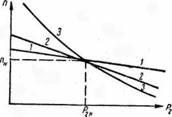
The armature speed of a DC motor is determined on the basis of the equation of the electrical state U = E + R I I I after substituting e into it. d.s. E = cfn:
 (13)
(13)
The voltage drop in the armature R I I I is small: at rated load it does not exceed 0.03 - 0.07 U nom.
Thus, the speed of a DC motor is directly proportional to the applied mains voltage and inversely proportional to the stator magnetic flux . It follows from equation (13) that the engine speed can be controlled in two ways: by changing the stator flux Ф or the voltage U supplied to the engine. The speed control by changing the magnetic field of the machine is carried out using an adjusting rheostat in the engine excitation circuit. The voltage supplied to the motor is changed by adjusting the source voltage.
You can add an additional rheostat to the armature circuit. In this case, the starting rheostat is replaced by a starting rheostat. Equation (13) then has the form
 (14)
(14)
From this it follows that the regulation of the engine speed can be carried out by changing the mains voltage, the resistance of the ballast rheostat or the stator flux.
Engine reversal. From the equation of the engine torque M em \u003d kFI i, it follows that reversal, i.e., changing the direction of rotation of the armature, can be carried out by changing the direction of the current in the excitation winding (flux Ф) or the armature current.
To reverse the motor “on the go”, the direction of the armature current is changed (by switching the armature leads), and the excitation winding is not switched, since it has a large inductance and breaking its circuit with current is unacceptable. Reversing the disconnected motor is also carried out by changing the direction of the current in the field winding (switching its outputs).
Ministry of Education and Science of the Russian Federation
SEI VPO South Ural State University
Branch in Zlatoust
DC motors
ZD-431.583.270102
Completed by: Sharipova Yu.R.
Group: ZD-431
Checked by: Rumyantsev.E.
1. Introduction
2. The device and principle of operation of DC motors
3. Starting engines
4. Technical data of motors
5. Efficiency of DC motors
6 DC motor characteristics
6.1 Performance data
6.2 Mechanical characteristic
7. List of used literature
1. Introduction
DC electrical machines are widely used in various industries.
The significant distribution of DC electric motors is explained by their valuable qualities: high starting, braking and overload torques, relatively high speed, which is important when reversing and braking, the possibility of wide and smooth speed control.
DC motors are used for adjustable drives, for example, for drives of various machines and mechanisms. The power of these electric motors reaches hundreds of kilowatts. In connection with the automation of the control of production processes and mechanisms, the scope of application of low-power general-purpose DC motors with power from units to hundreds of watts is expanding.
Depending on the power circuit, the excitation windings of a DC machine are divided into several types (with independent, parallel, serial and mixed excitation).
The annual output of DC machines in the Russian Federation is much less than the output of AC machines, which is due to the high cost of DC motors.
At first, direct current machines were created. In the future, they were largely replaced by AC machines. Due to the possibility of smooth and economical rotation speed control, DC motors retain their dominant role in transport, for driving metallurgical machines, in cranes and hoisting and transport mechanisms. In automation systems, DC machines are widely used as executive motors, motors for driving self-recording tape mechanisms, as tachogenerators and electric machine amplifiers.
2. The device and principle of operation of DC motors
The device of DC machines (generators and motors) is shown in a simplified form in Fig.1. The main 2 and additional 4 poles are attached to the steel case 1 of the stator of the machine. The excitation winding 3 is located on the main poles, the winding of additional poles 5 is located on the additional poles. The excitation winding creates a magnetic flux F of the machine.
Fig.1
A cylindrical magnetic circuit 6 is fixed on the motor shaft 10, in the grooves of which the armature winding 7 is located. The sections of the armature winding are attached to the collector 9. Fixed brushes 8 are pressed against it by springs. The collector fixed to the motor shaft consists of a number of copper plates. With the help of a collector and brushes, the armature winding is connected to an external electrical circuit. In motors, they also serve to convert the current of the external circuit, which is constant in direction, into a current that changes in direction in the conductors of the armature winding.
Additional poles with a winding located on them reduce sparking between the brushes and the commutator of the machine. The winding of the additional poles is connected in series with the armature winding and is often not shown on electrical circuits.
To reduce power losses, the armature magnetic core is made of separate steel sheets. All windings are made of insulated wire. In addition to motors with two main poles, there are DC machines with four or more main poles. In this case, the number of additional poles and sets of brushes increases accordingly.
If the motor is connected to a DC voltage network, then the interaction of the magnetic field created by the excitation winding and the current in the armature conductors causes a torque acting on the armature:
![]() (1)
(1)
where K M is a coefficient depending on the design parameters of the machine; Ф - magnetic flux of one pole; I I - armature current.
If the motor torque at n = 0 exceeds the braking torque that the motor is loaded with, then the armature will begin to rotate. With an increase in the rotational speed n, the EMF induced in the armature increases. This leads to a decrease in the armature current:
![]() (3)
(3)
where r I is the armature resistance.
The consequence of a decrease in current I I is a decrease in engine torque. When the engine and load torques are equal, the rotational speed stops changing.
The direction of the motor torque, and therefore the direction of rotation of the armature, depends on the direction of the magnetic flux and current in the conductors of the armature winding. To change the direction of rotation of the motor, it is necessary to change the direction of the armature current or the field current.
3. Starting engines
From formula (3) it follows that in the first instant after the engine is switched on in the DC voltage network, i.e. when and ,
Since the resistance r I is small, the armature current can be 10 ... 30 times higher than the rated current of the motor, which is unacceptable, since it will lead to strong sparking and destruction of the collector. In addition, at such a current, an unacceptably large motor torque occurs, and with frequent starts, overheating of the armature winding is possible.
To reduce the starting current in the armature circuit, a starting resistor is included, the resistance of which decreases to zero as the engine speed increases. If the engine start is automated, then the starting resistor is made up of several stages, which are turned off in series as the speed increases.
Armature starting current
![]()
As the engine accelerates, the EMF increases in the armature winding, and as follows from formula (3), this leads to a decrease in the armature current I I. Therefore, as the engine speed increases, the resistance in the armature circuit decreases. In order to obtain a large starting torque with a relatively small starting current, the motor is started with the highest magnetic flux. Therefore, the excitation current at start-up should be the maximum allowable, i.e. nominal.
4.Technical data of motors
The following technical data are indicated in the motor passport and reference literature for DC motors: rated voltage U and, power P n, rotational speed n n, current I n, efficiency.
Under the nominal U n understand the voltage for which the armature winding and collector are designed, as well as in most cases the parallel field winding. Taking into account the rated voltage, the electrical insulating materials of the motor are selected.
Rated current I n - the maximum allowable current (consumed from the network), at which the engine heats up to the highest allowable temperature, operating in the mode (long-term, intermittent, short-term) for which it is designed:
![]()
where I yan - armature current at rated load; I ext - excitation winding current at rated voltage.
It should be noted that the excitation current I vn of the parallel excitation motor is relatively small, therefore, at rated load, it is usually taken
Rated power R n is the power developed by the engine on the shaft when operating with a rated load (torque) and at a rated speed n n.
The rotational speed n n, and the efficiency correspond to the operation of the motor with current I n, voltage U n without additional resistors in the motor circuits.
In the general case, the power on the shaft P 2, the moment M and the rotational speed n are related by the relation:
The power consumed by the engine from the network P 1, the values P 2, efficiency, U, I are related by the relations:
It is obvious that these ratios are also valid for the nominal mode of operation of the engine.
5. Efficiency of DC motors
Efficiency is the most important indicator of DC motors. The larger it is, the less power P and current I consumed by the motor from the network at the same mechanical power. In general, the dependency is as follows:
![]() (9)
(9)
where - losses in the armature winding; - losses in the excitation winding; - losses in the armature magnetic circuit; - mechanical losses.
Power losses do not depend, and little depend on the engine load.
Motors are calculated in such a way that the maximum efficiency value is in the area close to the rated power. The operation of engines at low loads is undesirable due to the small values of r i. The efficiency values of engines with different excitation methods and power from 1 to 100 kW at rated load are different and average 0.8.
6. Characteristics of DC motors
6.1. Operating characteristics
Workers are called adjusting, high-speed, torque and efficiency. characteristics.
Control characteristic
The control characteristic represents the dependence of the rotation speed P on the excitation current Ib if the armature current Ia and the network voltage U remain unchanged, i.e. n=f(Iv) at Ia=const and U=const.
As long as the steel of the magnetic drive of the machine is not saturated, the flux Ф changes in proportion to the excitation current Iв. In this case, the control characteristic is hyperbolic. With saturation at high currents Iv, the characteristic approaches linear (Fig. 2). At low values of current Iv, the rotation speed increases sharply. Therefore, when the excitation circuit of the engine is broken (Iv \u003d 0) with parallel excitation, the speed of its rotation reaches unacceptable limits, as they say: "The engine is running wild." An exception may be micromotors, which have a relatively large idle torque M0.

Rice. 2. Adjusting characteristic of the engine
In series excitation motors, Iv \u003d Ia. At low loads, the armature current Ia is small and the rotation speed can be too high, so starting and operating at low loads are unacceptable. Micromotors as well. in the previous case, may constitute an exception.
speed characteristics.
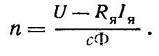
The speed characteristics give the dependence of the rotation speed n on the useful power P2 on the motor shaft if the voltage U of the network and the resistance rv of the control rheostat of the excitation circuit remain unchanged, i.e. n=f(P2), with U=const and rв = const .
Rice. 3. Speed characteristics
With an increase in the armature current with an increase in the mechanical load of the shunt motor, the voltage drop in the armature simultaneously increases and an armature reaction occurs, which usually acts in a demagnetizing manner. The first reason seeks to reduce the speed of rotation of the engine, the second - to increase. The effect of the voltage drop in the armature usually has a greater effect. Therefore, the speed characteristic of the parallel excitation motor has a slightly falling character (curve 1, Fig. 3).
In a series excitation motor, the armature current is the excitation current. As a result, the speed characteristic of an engine with sequential excitation has a character close to hyperbolic. As the load increases as the magnetic circuit becomes saturated, the characteristic becomes more straightforward (curve 3 in Fig. 3).
In a compound motor, when the windings are turned on consonantly, the speed characteristic occupies an intermediate position between the characteristics of a parallel and series excitation motor (curve 2).
Moment characteristics.
The torque characteristics show how the moment M changes with a change in the useful power P2 on the motor shaft, if the voltage U of the network and the resistance rv of the control rheostat in the excitation circuit remain unchanged, i.e. M = f(P2), with U=const, rv= const.
Useful moment on the motor shaft
If the rotational speed of the parallel excitation motor did not change with the load, then the dependence of the moment Mmex on the net power would graphically represent a straight line passing through the origin. In fact, the speed of rotation decreases with increasing load. Therefore, the characteristic of the useful moment is somewhat bent upwards (curve 2, Fig. 4). In this case, the curve of the electromagnetic moment M passes above the curve of the useful moment Mmex by a constant value equal to the idle moment M0 (curve 1).
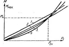
Rice. 4. Moment characteristics
In a series excitation motor, the type of torque characteristic approaches parabolic, since the change in torque from the load current occurs, according to the parabola law, until the steel is saturated. With saturation, the dependence becomes more straightforward (curve 4). In a compound motor, the torque characteristic (curve 3) occupies an intermediate position between the characteristics of a parallel and series excitation motor.
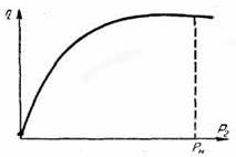
Characteristics of the change in efficiency.
The curve of dependence of efficiency on load has a form characteristic of all engines (Fig. 5). The curve passes through the origin and grows rapidly as the useful power increases to 1/4 of the nominal power. At a power P2 equal to about 2/3 of the rated power, the efficiency usually reaches its maximum value. When the load increases to the nominal efficiency, it remains constant or drops slightly.
Rice. 5. Change in engine efficiency
6.2 Mechanical characteristic
The most important characteristic of the engine is the mechanical n(M). It shows how the engine speed depends on the developed torque. If nominal voltages are applied to the motor windings and there are no additional resistors in its circuits, then the motor has a mechanical characteristic called natural. On the natural characteristic there is a point corresponding to the nominal data of the engine (M n, P i, etc.). If the voltage on the armature winding is less than the nominal, or I in< I вн, то двигатель будет иметь различные искусственные механические характеристики. На этих характеристиках двигатель работает при пуске, торможении, реверсе и регулировании частоты вращения.
Transforming expression (3) with respect to the rotation frequency, we obtain the equation of the electromechanical characteristic n(I i):
![]() (7)
(7)
After replacing the current I i in equation (7) according to formula (1), we obtain the equation of the mechanical characteristic n (M):
![]() (8)
(8)
When Ф = const, the electromechanical n (I I) and mechanical n (M) characteristics of the parallel excitation motor are straight lines. Since the magnetic flux changes slightly due to the armature reaction, the characteristics actually differ somewhat from straight lines.
When idling (M = 0), the engine has an idle speed determined by the first term of equation (8). As the load increases, n decreases. As follows from equation (8), this is due to the presence of armature resistance r i.
Since r i is not large, the engine speed changes little with an increase in torque, and the engine has a rigid natural mechanical characteristic (Fig. 6, characteristic 1).
From equation (8) it follows that there are three ways to control the rotational speed for a given constant load (M = const):
a) a change in the resistance of the armature circuit;
b) change in the magnetic flux of the motor;
c) voltage change at the armature terminals.

Rice. 6 Mechanical characteristics
To control the speed of rotation in the first way in the armature circuit. additional resistance r d must be included. Then the resistance in equation (8) must be replaced by r i + r d.
As follows from equation (8), the rotational speed n is related to the resistance of the armature circuit r i + r d at a constant load (M = const) by a linear relationship, i.e. as the resistance increases, the speed decreases. Different resistances r d correspond to various artificial mechanical characteristics, one of which is shown in Fig. 2 (characteristic 2). Using characteristic 2, with a given torque M1, you can get the speed n2.
Changing the speed in the second way is carried out using an adjustable voltage source UD2. By changing its voltage with the regulator R2, it is possible to change the excitation current I V and thereby the magnetic flux of the motor. As can be seen from equation (8), at a constant load (M = const), the rotation frequency is in a complex dependence on the magnetic flux Ф. Analysis of equation (8) shows that in a certain range of magnetic flux Ф, a decrease in the latter leads to an increase in the rotation frequency. It is this range of flow change that is used in speed control.
Each value of the magnetic flux corresponds to an artificial mechanical characteristic of the engine, one of which is shown in Fig. 2 (characteristic 4). With the help of characteristic 4 at the moment M1, you can get the speed n4.
In order to regulate the speed of rotation by changing the voltage at the armature terminals, it is necessary to have a relatively powerful regulated voltage source. Each voltage value corresponds to an artificial mechanical characteristic of the engine, one of which is shown on fig.2(characteristic 3). Using characteristic 3, with a given torque M1, you can get the speed n3.
Bibliography
1. Katsman M.M. Electric cars. -M.: Higher. school, 1993.
2. Kopylov I.P. Electric cars. -M.: Energoatomizdat, 1986
DC motors can have independent, parallel, series or mixed excitation (Fig. 6.1).
Rice. 6.1. Independent DC motor circuits ( a),
parallel ( b), sequential ( in) and mixed ( G) excitation
(the upper part of the scheme "c" belongs to the scheme "a")
In a parallel excitation motor, the field winding is connected in parallel to the armature terminals. But the current flowing through this winding, unlike the armature current, does not depend on the load and is determined by the voltage applied to the armature and the total resistance of the excitation circuit. For this reason, a shunt-excited motor is also called an independent-excited motor.
Torque M DC motor and its EMF E are determined by the formulas
M= to F I I; E= kФω,
where k is the design coefficient of the engine;
Ф – magnetic flux, Wb;
I i - armature current, A.
ω is the angular velocity, rad/s.
Electromechanical equations ω = ƒ ( I i) and mechanical ω = ƒ ( M) of characteristics have the form
ω = U/(kF) – ( R i + R p) / (k F) I I;
ω = U/(kF) – ( R i + R p) / (to 2 F 2) M.
Angular speed of ideal idle (at I i = 0 or M = 0)
ω 0 = U/(kF).
On fig. 6.2 presents the mechanical characteristics of a DC motor with independent excitation (DPT NV) in all operating modes. The characteristic points of the characteristics in the motor mode are: the point of ideal idle (ω 0, M= 0); nominal mode point (ω n, M n); short circuit point (ω = 0, M = M to).
The rigidity of the mechanical characteristic is determined by the excitation flux and the resistance of the anchor circuit:
β = d M/dω = - to 2 Ф 2 / ( R i + R p) = - M to / ω.
Rice. 6.2. Combined mechanical characteristics of a DC motor with independent excitation
The highest value of the stiffness modulus corresponds to the natural mechanical characteristic, since the excitation current is equal to the rated current and the control resistance R p \u003d 0. As the resistance of the rheostat increases R p the slope of the mechanical characteristic increases, and the angular velocity decreases. For a given resistance value R p and rated torque M n engine angular speed
ω n.r = ω 0 (1 – I n ( R i + R R) / U n.
To calculate the mechanical characteristics, it is necessary to know the armature resistance of the motor R i, which is specified in directories. In the absence of factory data, the value R I find approximately by the formula
R i \u003d 0.5 (1 - ŋ n) ( U n/ I n).
Since the mechanical characteristics of the DPT NV are straightforward, it is enough to have two points to plot them:
1) ω = ω 0 and M = 0,
2) ω = ω n (or ω = ω n.r) and M = M n.
For DPT NV, the following three modes of electric braking are possible.
1. Regenerative braking, which occurs when the engine speed is above ideal idle speed. It is the most economical, since the braking energy is transferred to the electrical network. The mechanical characteristics in this mode are a continuation of the corresponding characteristics of the motor mode in the II quadrant. The motor circuit does not change during regenerative braking.
2. Dynamic braking. The motor armature is disconnected from the network and shorted to resistance. In this case, the mechanical energy of the moving parts (mechanism and motor armature) is converted into electrical energy, which is lost in the form of thermal energy in the resistance of the anchor circuit. The mechanical characteristics in this braking mode pass through the origin (in Fig. 6.2 - lines with three notches).
3. Reverse braking carried out in two ways:
1) the introduction of high resistance in the armature circuit. In this case, the motor torque becomes less than the static load torque. M With. The engine stops (at point A), and then under the influence of torque M c starts to rotate in the other direction, developing a braking torque; at point B, the steady state occurs. Mechanical characteristics are a continuation of the corresponding characteristics of the motor mode (in Fig. 6.2 - lines with four serifs);
2) braking by switching the polarity of the armature winding along the way. Engine running at point 1 , after switching it will switch to the rheostatic characteristic at the point 2. Along the line 2–3 deceleration occurs (line with five serifs). At the point 3 the motor stops and must be disconnected from the mains to avoid switching to motoring mode with reverse rotation.
AT DC motor with series excitationde-niem the armature current is also the excitation current. The excitation magnetic flux increases with increasing load, as a result of which the angular velocity decreases according to equation (6.1) and the mechanical characteristic of the motor will be soft (Fig. 6.3). Thanks to this, the NV DPT overcomes overloads relatively easily and smoothly and has a high starting torque. These properties of the engine allow it to be widely used in the drive of transport mechanisms. The mechanical characteristics of the engine are significantly softened when a rheostat is introduced into the armature circuit (Fig. 6.3, lines with one notch).
Rice. 6.3. Mechanical characteristics of DC motor
with sequential excitation
In DPT PV, it is impossible to implement the regenerative braking mode, since there is no ideal idle speed in it.
Dynamic braking can be carried out according to the scheme with self-excitation and with independent excitation. In the first case, the armature and the excitation winding are disconnected from the network and closed to the rheostat. To avoid degaussing the machine, it is necessary to switch the excitation winding (or armature) so that the direction of the current in the excitation winding does not change. In this case, the machine is self-excited at a given resistance of the armature circuit only at a certain value of the angular velocity; excited, it creates a braking moment. Mechanical characteristics are non-linear (in Fig. 6.3 - curves with four notches).
The mechanical characteristics of the engine in the mode of dynamic braking with independent excitation are similar to the corresponding characteristics of the engine with independent excitation (in Fig. 6.3 - lines with two notches). This method of braking has found wide application, and the first method is rarely used, mainly as an emergency, for example, when the mains voltage fails.
Braking by opposition is carried out, as in DPT NV, in two ways:
1) inclusion in the armature circuit of high resistance;
2) by changing the polarity of the armature winding, leaving the direction of the current in the excitation winding unchanged.
With the first method, the mechanical characteristic will be a continuation of the characteristic corresponding to the motor mode (in Fig. 6.3 - a line with three notches). In the second method, braking is carried out along the line 1 –2–3 .
Speed control of direct current electric drives. The speed of the DPT NV can be adjusted:
1) by changing the resistance in the armature circuit;
2) change in the flow of excitation;
3) by changing the voltage supplied to the armature.
Regulation according to the first method has significant disadvantages:
- the rigidity of the mechanical characteristics decreases with a decrease in the angular velocity, and the power losses in the main circuit increase;
- the control range is limited, especially at low loads;
– small smoothness and accuracy of regulation.
For these reasons, this type of regulation is rarely used in a DC drive.
By second way it is possible to regulate the magnetic flux only in the direction of decrease (since in the nominal mode the magnetic circuit of the motor is saturated), which corresponds to an increase in speed above the nominal one. The possible speed control range does not exceed 2 for a standard motor. The upper speed limit is limited by the mechanical strength of the engine armature elements - armature winding bandages, collector.
The main way to control the speed of DPT NV is a method based on changing the voltage supplied to the armature, which is carried out using a special adjustable converter. Thyristor converters are mainly used as individual power sources. The rigidity of the mechanical characteristics of the drive according to the system "converter - DCT NV" is almost constant. Mechanical characteristics are a family of straight lines parallel to each other. The range, smoothness, and accuracy of regulation are higher here than with other methods of regulation. Therefore, this drive system is used for mechanisms that require deep and smooth speed control.
Calculation of additional resistors in the DPT NV armature circuit. If the natural electromechanical or mechanical characteristic is known 1 engine (Fig. 6.4) and its passport data, then the calculation of the resistance R d, when included in the armature circuit, the desired artificial characteristic 2 will pass through point A with given coordinates ω and, I and or ω and, M and, can be performed by the following most common methods.
Rice. 6.4. Characteristics of DPT HB for calculating the value
control resistors
Proportion method. Let us write the ratio of the speed drops at the current I and or moment M and on the natural Δω e and the desired artificial Δω and characteristics:
Δω e / Δω u = I and R I / ( I and ( R i + R e)) = R I / ( R i + R e).
Then the desired value
R d = R i (Δω and / Δω e - 1).
Segment method does not require knowledge of the value of the internal resistance of the motor R i (moreover, its value can be determined by a known natural characteristic).
Let's write an expression for the motor speed on a given artificial characteristic (see Fig. 6.4) at rated current I n, moment M n, magnetic flux F n and voltage U n:
ω and = U n / (kF n) (1 - I n R/ U n),
where U n / (kF n) \u003d ω 0.
ω and = ω 0 (1 – R / R n).
Here R n = U n/ I n - the so-called nominal resistance, which is the base value in the calculations, Ohm.
Ratio
R / U n \u003d (ω 0 - ω and) / ω 0 \u003d δ
reflects an important property of the NV DPT: the relative speed difference δ \u003d Δω / ω 0 is equal to the relative active resistance of the armature circuit R / R n.
Let's designate in fig. 6.4 characteristic points a, b,With, d and note that ω 0 – ω and = Δω = ace, ω 0 = ad. Then R = R n Δω / ω 0 = R n ace/ad; R d = R n bWith/ad; R i = R n ab /ad.
Thus, to find R d you must first determine the length of the segments according to the characteristics bWith and ad at rated current or torque and calculate the rated resistance R n = U n/ I n.
The calculation of additional resistors can also be performed using the following formulas for a given allowable current I additional, which is determined by the value of the allowable moment M additional or conditions for starting, reversing and braking.
Resistor resistance R d1 at start ( E = 0)
R q1 = ( U / I add) - R I.
Resistor resistance R d2 during dynamic braking
R q2 = ( E / I add) - R i ≈ ( U / I add) - R I).
Resistor resistance R d3 when reversing or braking by anti-switching
R d3 = (( U + E) / I add) - R i ≈ (2 U / I add) - R I.
Example . DPT NV type PBST-53 has the following passport data: R n = 4.8 kW; n n = 1500 rpm; U n = 220 V; I n = 24.2 A; R i = 0.38 ohm; I v.n = 0.8 A. It is required to determine:
1) the resistance of the resistor, the inclusion of which in the motor armature circuit will ensure the passage of an artificial mechanical characteristic through a point with coordinates ω and = 90 rad/s, M n = 25 Nm;
2) the resistance of the resistors, the inclusion of which will limit the current during start-up and braking by opposition to the level I add = 3 I n.