All fuses are switching electrical elements, designed to turn off the protected circuit by melting special protective elements. For the manufacture of fusible elements, lead, its various alloys, as well as copper or zinc, are used. Fuses protect Electricity of the net and equipment in case of short circuits and unacceptable prolonged overloads.
This property is very important for transformers and coils in switching networks, filters and many other applications. The extent to which a magnetic field can be stored at a given current in a coil is expressed by thermal inductance. Sometimes, however, the coil is also a disadvantage if it is undesirable to slow down the rapid change in current. This usually happens when components have too long connecting wires or leads. This is called leakage inductance.
An important formula is the definition of inductance. This is the most characteristic parameter of the coil. This formula is especially important for describing the electrical behavior of a coil with a known inductance. That the coil combines the voltage applied to its terminals and thus creates a magnetic field. The result is current through the coil. This is the opposite of a capacitor. This combines the current supplied to its terminals and thus creates an electric field. The result is the voltage between the terminals.
Function of the fuses
The normal operation of these devices is greatly affected by the current ratings of the fuses. It should be noted right away that all fuses can operate in two main modes. These are normal operating conditions, as well as unacceptable overloads and short circuits.
In the first case, the operation of the device occurs during the normal functioning of the network. Under such conditions, the fusible element is heated to the set operating temperature, when all the heat released gradually goes into the surrounding space. In this case, not only the protective element is heated to a certain temperature, but also other parts of the fuse. During normal operation, the temperature value should not exceed the allowable limits.
AT practical applications coils are usually wound on full windings with appropriate cores. The inductance is calculated. The value represents the reciprocal magnetic resistance of the coil and includes both geometry and core material. It is listed in the kernel data sheet, but can also be calculated. It is important to know that the inductance depends on the number of revolutions, i.e. with a double number of windings, a quadruple inductance is obtained.
For switching controllers, the following coil data are particularly important. Inductance wire resistance Maximum current current saturation. . Inductance measures how quickly current changes when voltage is applied. Usually minimum size coil required for ripple current, which must be exceeded, does not exceed a certain value. The inductance is not constant, but varies more or less with frequency or current, depending on the current core. Iron-containing cores, in particular, have a pronounced dependence of frequency and current inductance.
Using a fusible element
The fusible element is designed for the rated currents of the fuses, which ensure its continuous operation. In another way, this value is known as the rated current of the fusible element. It may differ from the same value provided for the fuse itself. This is due to the fact that elements designed for a different value can be inserted in the same fuse. The current value indicated on the device itself corresponds to the maximum current value for the elements intended for use in this design. The rated force provides an even distribution of the amount of heat from the material of the element to other parts of the fuse.
Therefore, the inductance with rated current is usually somewhat lower than the inductance without current. This must be taken into account when sizing the coil. Due to the strong current dependence, the inductance of iron powder core coils is often also given at rated current. Without a current load, the inductor is approximately 1.2-2.
However, in the case of coils with a ferrite core, the inductance is usually determined without a current load. Wire resistance, in particular, affects the efficiency of the circuit or limits the maximum allowable RMS current flowing through the coil. This corresponds to 20% of the input voltage! The maximum current is usually determined by heating the coil for a certain current. Often this is the moment when the coil turns, Often this is measured constant voltage or the effective value is displayed at low frequency.
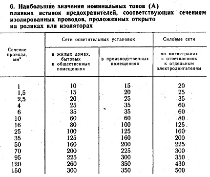
In the second case, the operation of the fuse occurs in conditions of increasing current in the network. In order to reduce the melting time of the insert, the protective elements are made in the form of plates with cutouts designed to reduce their cross section in some areas. More heat is released in the region of cutouts than in wide places.
When a coil is used in a switching regulator, this value is reduced by 50% because on the one hand the saturation current must be observed and on the other hand the core inside the coil is also heated by the component alternating current. Iron-containing cores, in particular, have fairly high core losses that are in the same range as losses due to wire resistance in conventional sizes. However, the peak current may exceed this current value as long as the rms value or heating is within the allowable range.
Therefore, in case short circuit there is intense heating of the narrowed sections and simultaneous burnout in several places at once. In this case, the current strength in the circuit does not have time to exceed the nominal value.
Thus, using fuse-links with different rated currents, it is possible to provide effective protection for various electrical equipment and electrical networks.
Saturation current is almost the most important criterion when choosing a coil, because if this value is too low, the coil is useless for the circuit. As already described for the inductor, this more or less depends on the coil current. If the current is further increased, the inductance decreases rapidly depending on the material of the core and the mechanical design, a decrease of 10 times is not uncommon.
The saturation current will never be exceeded with a properly configured switching regulator, since this limitation takes effect earlier. On the other hand, in case of poor design, the current limit is only indicated at high current, when the coil goes into saturation. This results in unnecessary losses and should therefore be avoided.
Hello, dear readers and guests of the Electrician's Notes website.
I decided to write an article about calculating the rated current for a three-phase electric motor.
This question is relevant and at first glance it seems not so complicated, but for some reason errors often occur in the calculations.
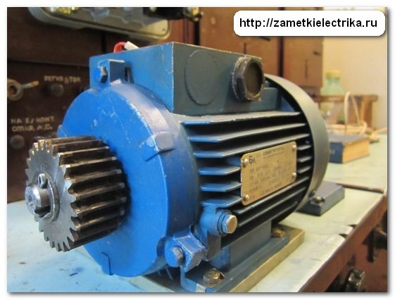
As an example for calculation, I will take a three-phase asynchronous motor AIR71A4 with a power of 0.55 (kW).
Since the inductance of the coil in saturation is minimal, it cannot store additional energy. Therefore, most of the energy flowing into the coil is converted to heat in the wire resistor or in the switching transistor, greatly reducing efficiency and possibly overshooting the switching regulator.
In a typical coil for switching power supplies, the saturation current is approximately 1.5-2 of the rated current. This allows the full use of the rated current, since the current ripple is about 50% of the rated current, the peak current is about 1.5 times the rated current.
Here is its appearance and tag with technical data.
The current defined by the limiting resistor can also occur on Idling no load, so low load does not protect against saturation! When a significant amount of energy needs to be stored in a coil due to an application, an air gap is needed. Most of the energy is then no longer stored directly in the nuclear material, but in the air gap. The larger the air gap, the more energy the coil can store, but it requires more windings to reach a certain inductance.
This applies to flyback converters as well as storage reactors in flow converters. For example, no air gap is required in a flux transformer transformer. Ferrite cores used in converters or current compensated chokes do not have an air gap. Therefore, they can hardly store energy and are therefore not suitable for storing reactors or inverters. Metal powder core rings go the other way: here, the minimal plastic spaces filled between the individual iron particles are already an air gap, so no additional air gap is needed.
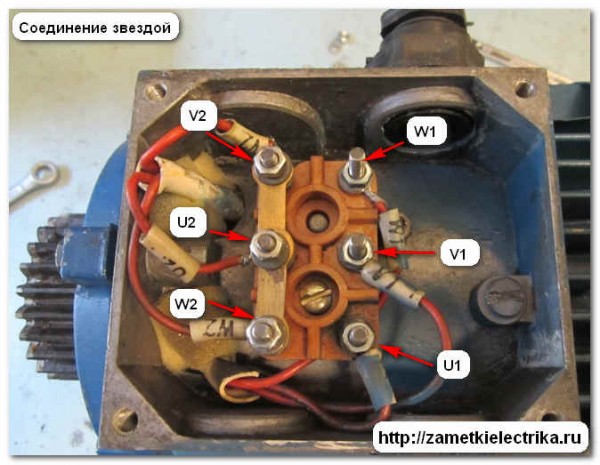
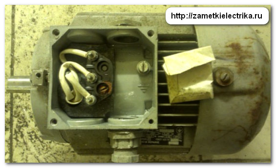
If you plan to connect the engine to three-phase network 380 (B), which means that its windings must be connected according to the “star” scheme, i.e. on the terminal block, it is necessary to connect the outputs V2, U2 and W2 to each other using special jumpers.
However, the materials used for this purpose have significantly higher magnetization losses than ferrite, so iron powder cores are usually only used for low frequencies. The most widely used material is yellow and white marked ring cores with material code. This is characterized primarily by low cost. Application range either in suppression chokes for DC or 50 Hz applications, or in switching networks up to 100 kHz. For higher frequencies, more expensive materials are better and of course available.
When connecting this motor to a three-phase network with a voltage of 220 (V), its windings must be connected in a triangle, i.e. install three jumpers: U1-W2, V1-U2 and W1-V2.
So let's get started.
Attention! The power on the nameplate of the engine is indicated not electrical, but mechanical, i.e. useful mechanical power on the motor shaft. This is clearly stated in the current GOST R 52776-2007, clause 5.5.3:
However, it should be noted that the inductance of a ferrite core is highly dependent on frequency, current, and also age! Depending on the temperature, the iron powder cores become more or less fast and the coil loses its inductance. The dimensions of the core of a ferro-percussion ring are not easy, as a large number of factors must be taken into account here. Basic loss calculation is also complicated, but some manufacturers provide formulas or calculation programs, Micrometals: Ring Powder Core Calculation Program.

Useful mechanical power referred to as R2.
Even more rarely, the tag indicates the power in horsepower(hp), but this I have never seen in my practice. For information: 1 (hp) \u003d 745.7 (Watts).
First of all, beginners are not advised on their own iron powder core coil sizes. Thus, iron powder is higher than ferrite, resulting in more compact coils with the same energy capacity. It is not uncommon for beginners to make the mistake of using the next coil with a suitable inductor without making sure that the coil is actually designed as an interference suppression coil. For example, in Reichelt. The chains work quite well, but the efficiency is much lower than with a good coil.
But we are interested in electric power, i.e. power consumed by the motor from the network. Active electrical power is denoted as P1 and it will always be greater than the mechanical power P2, because. it takes into account all losses of the engine.
1. Mechanical losses (Pmech.)
Mechanical losses include bearing friction and ventilation. Their value directly depends on the engine speed, i.e. the higher the speed, the greater the mechanical losses.
This is mainly due to the design of the coil and its existing core. RFI blocks are designed to pass low frequency current and to block low frequency current which is low compared to useful high frequency current. As a result, the magnetic field is constant or changes very slowly due to the low frequency current. Thus, the core is not designed for low loss, or even desirable if it has a certain loss per high frequencies to prevent resonances inside the coil.
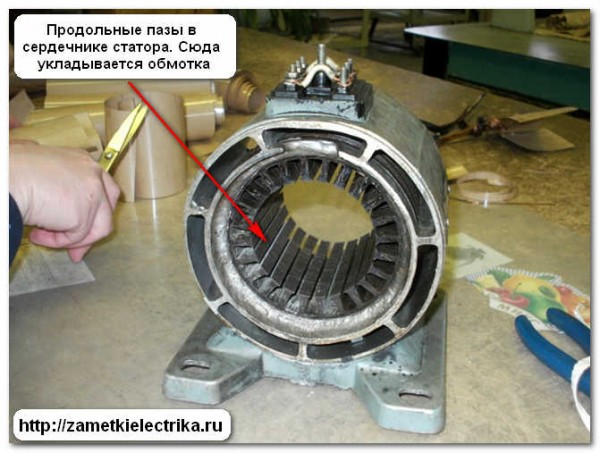
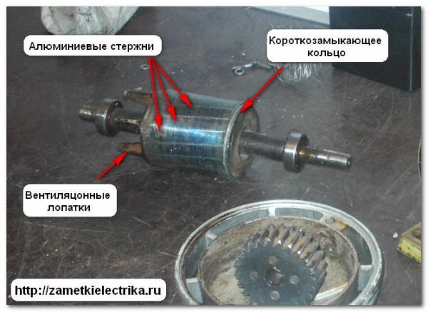
Asynchronous three-phase motors with a phase rotor, losses between brushes and slip rings are also taken into account. You can learn more about the design of asynchronous motors.

Thus, coils specifically designed for switching power supplies are often of appropriate mechanical design to keep the lines as strong as possible within or very close to the coil to minimize this interference.
Particularly for core-core coils, it must be checked exactly whether the data is applied for interference suppression applications or for switching power supplies: here the same coil is often defined differently depending on the intended use. This is because there is virtually no core loss during the application of noise suppression, and due to the lower heating, the wire can flow through a higher current without overheating.
2. Magnetic losses (Рmagn.)
Magnetic losses occur in the "hardware" of the magnetic circuit. These include hysteresis losses and eddy currents during core reversal.
The magnitude of magnetic losses in the stator depends on the frequency of magnetization reversal of its core. The frequency is always constant and is 50 (Hz).
Storage tanks: very good Suitable toroidal core coils: depending on the application Good to very good Resistor design, drum core: suitable for small energy suppression coils: poorly suited current limited chokes: absolutely unsuitable. Suitable coils for smaller switching regulators in any configuration, such as Reichelt or Konrad or similar coils. Thanks to the ferrite core, these coils are suitable for almost all frequency ranges.
The magnetic losses in the rotor depend on the frequency of the remagnetization of the rotor. This frequency is 2-4 (Hz) and directly depends on the amount of motor slip. But the magnetic losses in the rotor are small, so they are most often not taken into account in the calculations.
For buck controllers up to 100 kHz, especially at higher currents, they are often much cheaper than similar ferrite core coils. Here is a simple method for calculating coils. These are chokes for switching regulators and/or transformers for inverters. Also transformers and coils. This means that you simply and simply figured out your coil and wound it.
For amateurs, however, this usually results in satisfying results. talking in simple words, it can be said that the energy storage capacity of the coil is determined by the magnetic core. The number of turns does not matter! However, the energy remains the same, as the following formula shows. First you must calculate the required capacity. we will take as an example a boost switching regulator which requires a 330uH and 2.5A coil. The energy content is calculated.
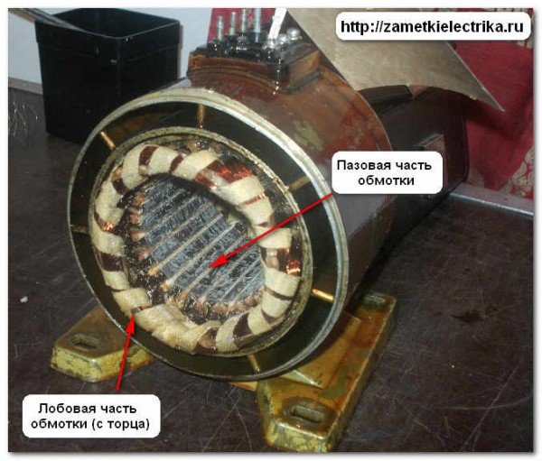
3. Electrical losses in the stator winding (Re1)
Electrical losses in the stator winding are caused by their heating from the currents passing through them. The greater the current, the more the motor is loaded, the greater the electrical losses - everything is logical.
4. Electrical losses in the rotor (Re2)
The electrical losses in the rotor are similar to the losses in the stator winding.
5. Other additional losses (Rdob.)
Additional losses include the higher harmonics of the magnetomotive force, the pulsation of magnetic induction in the teeth, and so on. These losses are very difficult to take into account, so they are usually taken as 0.5% of the consumed active power P1.
You all know what's in the engine Electric Energy converted to mechanical. If we explain in more detail, then when the electrical active power P1 is supplied to the motor, some of it is spent on electrical losses in the stator winding and magnetic losses in the magnetic circuit. Then the residual electromagnetic power is transferred to the rotor, where it is spent on electrical losses in the rotor and converted into mechanical power. Part of the mechanical power is reduced due to mechanical and additional losses. As a result, the remaining mechanical power is the useful power P2 on the motor shaft.
All these losses are included in a single parameter - the coefficient useful action(efficiency) of the engine, which is denoted by the symbol "η" and is determined by the formula:
By the way, the efficiency is approximately equal to 0.75-0.88 for engines with a power of up to 10 (kW) and 0.9-0.94 for engines over 10 (kW).
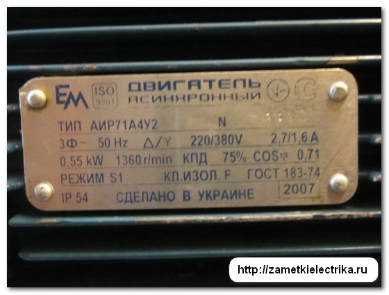
Once again, let us turn to the data of the AIR71A4 engine considered in this article.
Its nameplate contains the following information:
- engine type AIR71A4
- factory number XXXXX
- type of current - variable
- number of phases - three-phase
- mains frequency 50 (Hz)
- winding connection diagram ∆/Y
- rated voltage 220/380 (V)
- rated current in delta 2.7 (A) / in star 1.6 (A)
- rated net power on the shaft P2 = 0.55 (kW) = 550 (W)
- rotation speed 1360 (rpm)
- Efficiency 75% (η = 0.75)
- power factor cosφ = 0.71
- operating mode S1
- insulation class F
- protection class IP54
- company name and country of manufacture
- year of issue 2007
Calculation of the rated motor current
First of all, it is necessary to find the electrical active power consumption P1 from the network using the formula:
P1 \u003d P2 / η \u003d 550 / 0.75 \u003d 733.33 (W)
The power values are substituted into the formulas in watts, and the voltage is in volts. Efficiency (η) and power factor (cosφ) are dimensionless quantities.
But this is not enough, because we have not taken into account the power factor (cosφ ) , and the motor is an active-inductive load, therefore, to determine the total power consumption of the motor from the network, we use the formula:
S = P1/cosφ = 733.33/0.71 = 1032.85 (VA)
Find the rated current of the motor when the windings are connected to a star:
Inom \u003d S / (1.73 U) \u003d 1032.85 / (1.73 380) \u003d 1.57 (A)
Find the rated current of the motor when the windings are connected in a triangle:
Inom \u003d S / (1.73 U) \u003d 1032.85 / (1.73 220) \u003d 2.71 (A)
As you can see, the resulting values \u200b\u200bare equal to the currents indicated on the motor tag.
To simplify, the above formulas can be combined into one general. The result will be:
Inom = P2/(1.73 U cosφ η)
Therefore, in order to determine the motor rated current, it is necessary to this formula substitute the mechanical power P2, taken from the tag, taking into account the efficiency and power factor (cosφ), which are indicated on the same tag or in the passport for the electric motor.
Let's check the formula.
Motor current when the windings are connected to a star:
Inom \u003d P2 / (1.73 U cosφ η) \u003d 550 / (1.73 380 0.71 0.75) \u003d 1.57 (A)
Motor current when the windings are connected in a delta:
Inom \u003d P2 / (1.73 U cosφ η) \u003d 550 / (1.73 220 0.71 0.75) \u003d 2.71 (A)
I hope everything is clear.
Examples
I decided to give a few more examples with different types of engines and capacities. We calculate their rated currents and compare them with the currents indicated on their tags.
As you can see, this motor can only be connected to a three-phase network with a voltage of 380 (V), because. its windings are assembled into a star inside the motor, and only three ends are brought out to the terminal block, therefore:
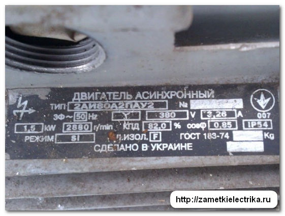
Inom \u003d P2 / (1.73 U cosφ η) \u003d 1500 / (1.73 380 0.85 0.82) \u003d 3.27 (A)
The resulting current of 3.27 (A) corresponds to the rated current of 3.26 (A) indicated on the tag.
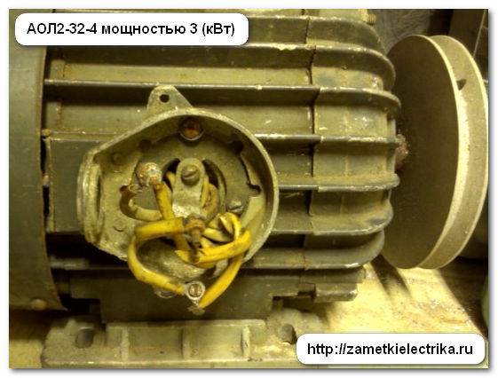
This motor can be connected to a three-phase network with a voltage of both 380 (V) star and 220 (V) triangle, because. it has 6 ends in the terminal block:
Inom \u003d P2 / (1.73 U cosφ η) \u003d 3000 / (1.73 380 0.83 0.83) \u003d 6.62 (A) - star
Inom \u003d P2 / (1.73 U cosφ η) \u003d 3000 / (1.73 220 0.83 0.83) \u003d 11.44 (A) - triangle
The obtained current values for different winding connection schemes correspond to the rated currents indicated on the tag.
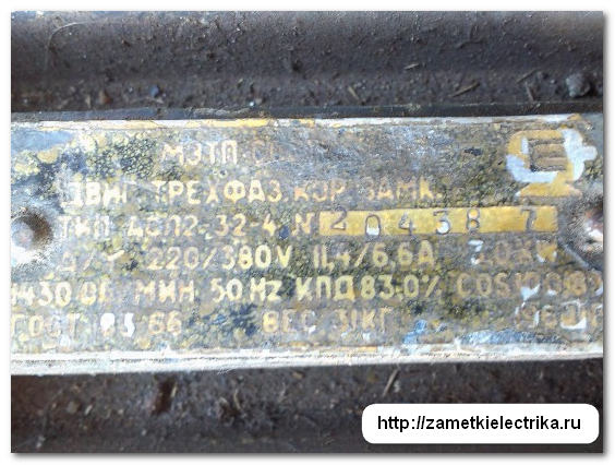
3. asynchronous motor AIRS100A4 with a power of 4.25 (kW)
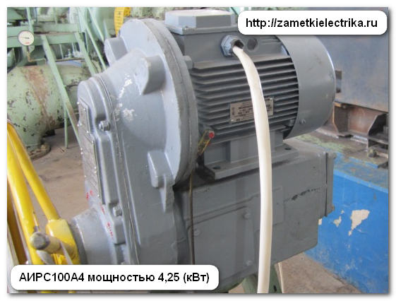

Similarly, the previous one.
Inom \u003d P2 / (1.73 U cosφ η) \u003d 4250 / (1.73 380 0.78 0.82) \u003d 10.1 (A) - star
Inom \u003d P2 / (1.73 U cosφ η) \u003d 4250 / (1.73 220 0.78 0.82) \u003d 17.45 (A) - triangle
The calculated values of the currents for different winding connection schemes correspond to the rated currents indicated on the nameplate of the motor.
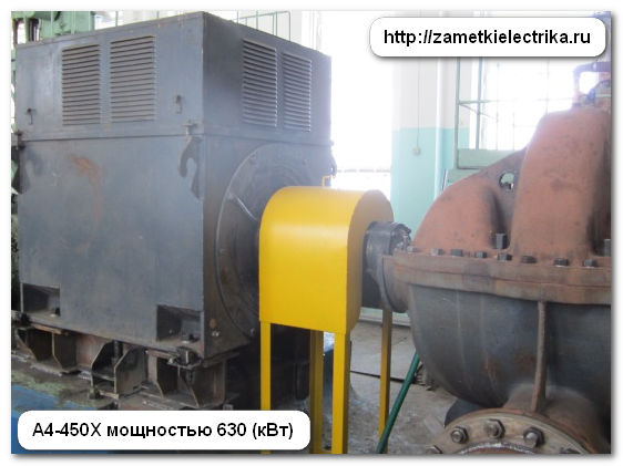
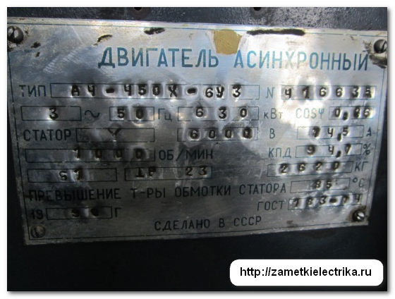
This motor can only be connected to a three-phase network with a voltage of 6 (kV). The connection scheme of its windings is a star.
Inom \u003d P2 / (1.73 U cosφ η) \u003d 630000 / (1.73 6000 0.86 0.947) \u003d 74.52 (A)
The rated current of 74.52 (A) corresponds to the rated current of 74.5 (A) indicated on the tag.
Addition
The above formulas are of course good and the calculation is more accurate, but there is a more simplified and approximate formula for calculating the rated motor current in the common people, which is most widely used among home craftsmen and craftsmen.
Everything is simple. Take the engine power in kilowatts indicated on the tag and multiply it by 2 - here you have the finished result. Only this identity is relevant for 380 (B) motors assembled in a star. You can check and multiply the power of the above engines. But personally, I insist you use more accurate calculation methods.
P.S. And now, as we have already decided on the currents, we can proceed to the selection of the circuit breaker, fuses, thermal protection of the motor and contactors for its control. I will tell you about this in my next posts. In order not to miss the release of new articles, subscribe to the newsletter of the Electrician's Notes website. See you again.