Stabilizers alternating current, are much less commonly used by radio amateurs than voltage stabilizers and power regulators. This is largely due to the more complex circuitry of traditional current sources. However, an objective analysis shows that in some cases it is preferable to use current sources. The main advantage of the current source is insensitivity to short circuit loads.
State-of-the-art roller carbon brushes help ensure smooth, fast response, good cooling, and limitless durability. It can be used in the harshest conditions. It is the result of 15 years of research, production and continuous improvement.
Experience and technological know-how have created a product durability, reliability and economy best suited to the requirements of the industry. Servo voltage regulators have been designed for harsh environments. Voltage stabilizers can be made with different features to suit your needs. A servo voltage regulator designed to protect against lighting, high voltage drop, high voltage, flicker and, if necessary, harmonics.
Quite often there are cases when it is necessary to maintain a constant value of alternating current, for example, when turning on powerful incandescent lamps. Such a measure prolongs their service life several times. Adjustable stabilizer can provide invaluable assistance in testing and setting up current protection devices.
Readers are offered a simple AC stabilizer circuit, with the possibility of smooth adjustment of its value. The current can be adjusted from a few milliamps up to 8 amps. With an appropriate choice of circuit elements, the maximum stabilized current can be increased to 70-80 A.
The servo-resistant stabilizer preserves the life of equipment installed on
It protects any electronic device connected to it from damage. A very good example is an automatic voltage stabilizer. There are various types of voltage regulators on the market. But we can also make them at home according to our needs and requirements.
Voltage stabilizer important points
Before building this device, consider the following points and specifications so that the device we have built can work properly and give us the desired results.
Automatic voltage stabilizer works
The microcontroller generates control signals and four are used with an autotransformer to control and convert the voltage. The input voltage is perceived by the microcontroller and tries to keep the output voltage between the specified ranges by switching the relay.The circuit is based on a current-stabilizing two-terminal network, this circuit solution has been known for a long time, but for a long time it was purely theoretical (remember what MOS transistors were 10-15 years ago). The situation changed with the advent of high-power MOS transistors (MOSFETs). Their use allows you to create current sources with good characteristics and extremely simple.
When the controller starts up, it checks the calibration. After successful calibration, we can remove the switch and variable resistor from the schema. The switch and variable resistor may only be needed now if we want to recalibrate the circuit, otherwise they are no longer needed in the circuit.
Voltage Stabilizer Relay and Transformer Tap
The configuration above shows the different taps of a transformer with a relay. In this circuit, we used a simple autotransformer. The auxiliary winding is used to power the circuit, and the ratio of turns is also shown. Both parts circuit diagram automatic voltage stabilizer are shown below.
Actually, the current stabilizer is assembled on an operational amplifier (op-amp) DA1, a transistor VT1 and resistors R1, R2, R4. The R1-R2 divider is a current "setter". In this case, the current in amperes is numerically equal to the voltage on the engine R2, multiplied by 10. This allows you to choose the voltage of the current sensor R4 is very small. To work with alternating current, a diode bridge is introduced into the circuit, one of the diagonals of which includes a current-stabilizing two-terminal network. This inclusion is equivalent to serial connection load and two-terminal, and, therefore, provides the same current through them.
This voltage will not change much because the circuit and relay will work to regulate this voltage as well. A decoupling capacitor is also used and is located next to the microcontroller. But not directly as the voltage is still a little higher rated voltage relay. So we pass this voltage through four diodes in series, which will reduce the voltage by 8V. The microcontroller controls the switching of the relay, but it cannot provide the current required to operate the relay, so we use transistors to amplify the current value.
Consider the current stabilization process in more detail. Since the rectified voltage is not filtered, the voltage at the drain of transistor VT1 is unipolar, pulsating. When the drain voltage (Figure 2A) is zero, no current flows through VT1 and the voltage drop across sensor resistor R4 is also zero. Transistor VT1 is fully open. As the voltage in the network increases, the voltage taken from the sensor also increases (in proportion to the flowing current), approaching the “setter” voltage. Transistor VT1 starts to close. If the voltages on the sensor R4 and on the “master” R1-R2 coincide, the further increase in current is limited. Op-amp DA1 maintains the same voltage at its inputs by changing the resistance of the channel VT1. This ensures the stabilization of the current. The shape of the current through VT1 coincides with the voltage on the "setter" and has a trapezoidal shape (Figure 2B). The same shape, only alternating, current flows through the load (Figure 2B). Elements VD1, R3, C1, C2 form a parametric stabilizer for powering the op-amp.
Coming to a seven-segment display, the three seven-segment displays used in the circuit are switched one after the other, minimizing the pins needed to move them. But it's happening so fast that we can't figure it out just by looking at them. The refresh rate is 167 Hz, i.e. The display is updated 167 times per second. To achieve the required brightness, we connected seven transistors with seven segments.
We used three in a diagram that shows delay, low cut or high cut, or just normal controller mode. It was the whole process of creating an automatic voltage stabilizer at home. By following the steps correctly, we hope you can do it at home too, and you can also modify it according to your requirements.

If you need to change the range of stabilized currents, you should appropriately select the type of transistor VT1 and diodes VD2-VD5, as well as adjust the voltage of the current "setter" or the resistance of the sensor R4.
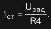
The stabilization current is determined by the formula:
I st. =U ass. /R4
The purpose of voltage stabilizers
Voltage stabilizers provide a constant amount of electrical current to electronic devices when power fluctuates in the home or business where the devices are located. Strong surges and sudden drops in power can cause serious damage to computers and other sensitive electronic devices. These stabilizers store and provide energy from their reserves to connected devices that do not go through energy fluctuations. Some of them are also included in the source uninterruptible power supply, which is a battery backup system that allows devices such as computers to continue working for a limited period of time in the event of a power failure.
Establishing the circuit comes down to controlling the voltage of the "setter" (so that the current does not go beyond 7 ... 8 A) and calibrating the control element (resistor R2). For visual control, an ammeter can be included in the current circuit.
OS DA1 any will do wide application(K140UD6, K140UD7, mA741, etc.). It is better to refrain from using high-speed op-amps with field-effect transistors, since the stabilizer can self-excite with them, which will inevitably disable the op-amp, the VT1 transistor and the bridge diodes (this is how the author’s circuit reacted to the K544UD2 installation). Transistor VT1 should be selected based on the maximum allowable drain current and drain-source voltage. Zener diode VD1 - any precision, with a stabilization voltage of 9 ... 15 V. The stability of the "master" voltage and, as a result, the stabilized current depends on its stability.
Operation of a standard voltage regulator
The details of how voltage regulators work vary from one type to another, but the basics remain the same. He connects to electrical outlet, which charges a series of capacitors or battery packs in a capacitor. These capacitors maintain charge even if the amount of electricity output fluctuates. Any device connected to the stabilizer draws power from capacitors or batteries instead of a direct output. The voltage regulator is wired so that the output and devices are on separate circuits.
Transistor VT1 should be mounted on a massive radiator. There are no special requirements for the rest of the details. Resistor R4 is conveniently made from an industrial shunt for measuring instruments. This will ensure the required accuracy and thermal stability. When installing it, special attention should be paid to the reliability of the connection of the inverted output of the op-amp and R4. A break in this connection causes the stabilizer to fail.
As the device drains power from the capacitors, the energy coming from the output will continue to charge them. Due to the resistance in the stabilizer circuit, its power on devices is less than the ideal output voltage. This means that devices may run slightly slower when connected to a voltage regulator.
Voltage stabilizers with amplifiers
To compensate for the lower power provided by the voltage regulator, some include an amplifier. This increases the input voltage that charges the capacitors or batteries, making sure they don't suffer from excessive power drain from the devices when the main power fluctuates. In many devices, the amplifier remains off when the output voltage is stable; the voltage should start to drop, but the amplifier is turned on to maintain D.C. on capacitors.
Current stabilizers are much less commonly used by radio amateurs than Surge Protectors and power regulators. This is largely due to the more complex circuitry of traditional current sources. However, an objective analysis shows that in some cases it is preferable to use current sources. The main advantage of the current source is its insensitivity to a short circuit of the load.
This allows devices to drain more power from capacitors or batteries. While this improves the performance of the voltage regulator and electronic devices, amplifiers increase the cost and overall size of the device. The most common on the market are stand-alone and line-interactive.
There are several online accessories, usually much more expensive models designed for industrial use or in addition to linear amplification, that include some sort of internal stabilizer. In them, the batteries are continuously charged and the inverter is constantly on, removing power from the batteries and supplying the equipment. This arrangement makes the equipment truly isolated from the mains, with input circuits and batteries absorbing all options.
Quite often there are cases when it is necessary to maintain a constant value of alternating current, for example, when turning on powerful incandescent lamps. Such a measure prolongs their service life several times. An adjustable stabilizer can provide invaluable assistance in testing and setting up current protection devices.
Readers are invited to a simple AC stabilizer circuit with smooth adjustment of its size. The current is adjustable from a few milliamps to 8 A. With an appropriate choice of circuit elements, the maximum stabilized current can be increased to 70 ... 80 A.
The problem is that online bonds are very expensive and therefore uncommon, reserved for servers and industrial applications. Apart from the price issue, online investors have poor energy efficiency due to double conversion. To improve efficiency, many manufacturers use hybrid layouts, where the circuitry monitors grid current and quickly switches online only when it has a change or noise level above a specified value.
In them electricity filtered and delivered directly to the equipment, just like an in-line filter. In parallel, we have batteries and an inverter that are quickly taken up in the event of a power failure. It takes a few milliseconds for the switching circuit to notice the drop in the mains and drive the inverter, so there is a short interruption in the supply of the equipment, which goes unnoticed by the power circuits.
The stabilizer circuit is shown in Fig. 1. It is based on a current-stabilizing two-terminal network, described in detail in. This circuit design solution has been known for a long time, but for a long time it was purely theoretical (remember what MOSFETs were 10 ... 15 years ago). The situation changed with the advent of powerful MOSFETs(MOSFET; firms Intersil and International Rectifiei. Their use allows you to create current sources with good characteristics and maximum simple diagrams(and the coincidence of calculations with practice pleasantly surprised the author).
The list includes line-interactive models, which are an evolution of offline work. Currently, there is a fourth category, which is the leader in the production of stroke marks, which are the popular version of the interactive interactive interface.
If the voltage drops below a certain limit, the inverter is activated and the batteries are finally used. Many models use multi-stage transformers, offering much smoother attenuation. Linear acceleration technology is much cheaper than line-interactive technology, so manufacturers use it on most models. Although they are also called "interactive-interactive", "interactive", or even "failed with online regulation", they are distinct from interactive or interactive interactive.
Actually, the current stabilizer is assembled on the op-amp DA1, the transistor VT1 and the resistors R1, R2, R4. The divider R1-R2 is a current generator. In this case, the current in amps is numerically equal to the voltage on the engine R2, multiplied by 10. This allows you to choose the voltage of the current sensor R4 is very small. To work with alternating current, a diode bridge is introduced into the circuit, one of the diagonals of which includes a current-stabilizing two-terminal network. Such an inclusion is equivalent to a series connection of a load and a two-terminal network, and, therefore, provides the same current through them.
The use of microprocessors and design improvements have made them much more reliable than older models, which greatly reduces the difference in practice. The drive of the converter has accelerated, and the use of capacitors and other circuits reduces the time to fall near zero. Efficiency has also improved significantly. Many modern models work with 95% efficiency.
They are at the base of the pyramid, but they are cheap and therefore not bad at all if you know how to deal with the limitations. This is a normal stand-alone UPS that does not attempt to stabilize the output voltage. Although the switching time is long and the power is too low, it has the slight advantage that it consumes little power. This makes it not a bad option for those who only want a line filter with a battery backup to prevent micro-shutdown with any light flashing.
Fig.1 Scheme of the AC stabilizer
Consider the current stabilization process in more detail. Since the rectified voltage is not filtered, the voltage at the drain of VT1 is unipolar, pulsating. When the drain voltage (Fig. 2a)is zero, no current flows through VT1, and the voltage drop across the sensor resistor R4 is also 0. The transistor VT1 is fully open. As the voltage in the network increases, the voltage taken from the sensor also increases (in proportion to the flowing current), approaching the voltage of the setpoint. Transistor VT1 starts to close.
If the voltages on the sensor R4 and on the generator R1-R2 coincide, the further increase in current is limited. Op-amp DA1 maintains the same voltage at its inputs by changing the resistance of the channel VT1. This ensures the stabilization of the current. The shape of the current through VT1 coincides with the voltage on the generator and has a trapezoidal shape (Fig. 2b).The same shape, only alternating, the current flows through the load (Fig. 2c).Elements VD1, R3, C1, C2 form a parametric stabilizer for powering the op-amp.
Output Format: Another important feature is the output format of the inverter. When the UPS is using batteries, the inverter must convert the batteries' DC current into AC current. Basically, DC is a straight and constant line, while AC is an analog wave that oscillates 60 times per second.
They are a bit dangerous as they can damage sensitive devices or even micro power supply if there are frequent power outages. The latest cheap models use an almost sinusoidal, half wave, where the variations are done at large intervals, offering something closer to an analog wave. Finally, we have the most expensive models that generate "pure" sine waves, that is, almost identical to those provided by electrical network. They are naturally best within the subject.
If you need to change the range of stabilized currents, you should select the type of transistor VT1 and diodes VD2 ... VD5 accordingly, as well as adjust the voltage of the current generator (U set) or the resistance of the sensor R4.
The stabilization current is determined by the formula:
This circuit can also be converted to an active AC load, how to do this is described in detail in.
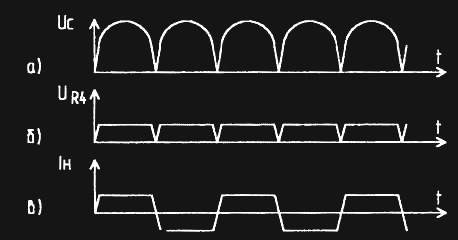
Rice. 2 Signal diagram
Establishing the circuit comes down to controlling the voltage of the setting device (so that the current does not go beyond 7 ... 8 A) and calibrating the control element (resistor R2). For visual control, an ammeter can be included in the current circuit.
Op-amp DA1 is suitable for any wide application (K140UD6, K140UD7, mA741, etc.). It is better to refrain from using high-speed op-amps with field-effect transistors, since the stabilizer can self-excite with them, which will inevitably disable the op-amp, the VT1 transistor and the bridge diodes (this is how the author’s circuit reacted to the K544UD2 installation). Transistor VT1 should be selected from the range of the above companies, focusing on the maximum allowable drain current and drain-source voltage. The zener diode VD1 is any precision one, with a stabilization voltage of 9 ... 15 V. The stability of the generator voltage and, as a result, the stabilized current depends on its stability.
Transistor VT1 should be mounted on a massive radiator. There are no special requirements for the rest of the details. Resistor R4 is conveniently made from an industrial shunt for measuring instruments. This will ensure the required accuracy and thermal stability. When installing it, special attention should be paid to the reliability of the connection of the inverted output of the op-amp and R4. A break in this connection causes the stabilizer to fail.
A. Uvarov
Literature
1. Uvarov A.S. Resistive load - current source. - Radio amateur, 2001, N1, p.14.
2. Ivanov P., Semushkin S. Stable current sources and their application in radio equipment. - To help the radio amateur. Issue. 104. - M.: DOSAAF, 1989.
3. http://www.intersil.com
4. Powerful field-effect switching transistors from International Rectifier. - Radio, 2001, N5, p.45.