1. PURPOSE OF MEASUREMENTS.
Measurements are carried out in order to verify that the insulation resistance complies with established standards.
2. SECURITY MEASURES
2.1. Organizational events
AT electrical installations with voltages up to 1000 V, measurements are performed by order of two employees, one of whom must have an electrical safety group of at least III.
AT electrical installations up to 1000 V, located in rooms, except for those that are especially dangerous in terms of damage electric shock, an employee who has group III and the right to be a foreman can carry out measurements alone.
It is allowed to measure the insulation resistance of the rotor of a running generator by order of two employees who have IV and III electrical safety groups.
AT In cases where measurements with a megohmmeter are included in the scope of testing work (for example, testing electrical equipment with increased voltage of industrial frequency), these measurements are not required to be specified in the order or order.
The provisions of this methodology are mandatory for use by specialists electrical laboratories in Krasnodar and the Krasnodar Territory LLC "Energo Alliance"
2.2. Technical measures
The list of necessary technical measures is determined by the person issuing the order or order in accordance with the requirements of the PETEE. Insulation resistance measurements with a megohmmeter should be carried out on disconnected current-carrying parts, from which the charge has been removed by preliminary grounding. Grounding from current-carrying parts should be removed only after connecting a megohmmeter.
3. RATED VALUES
The frequency of tests and the minimum allowable value of insulation resistance must comply with those specified in the test standards for electrical equipment and apparatus of the Electrical Installation Rules (PUE), Rules technical operation electrical installations of consumers (PTEEP). In accordance with GOST R 50571.16-99, the normalized values of the insulation resistance of electrical installations of buildings are given in table 1
Table 1.
|
Rated circuit voltage, V |
DC test voltage, V |
Insulation resistance, MOhm |
|
Safety extra low voltage systems (BSSN) and functional extra low voltage FSSN) |
0.25 |
|
|
Up to 500 inclusive, except for BSSN and FSSN systems |
0.5 * |
|
|
Above 500 |
1000 |
1.0 |
* The resistance of stationary household electric stoves must be at least 1 MΩ.
However, in accordance with Chap. 1.8 PUE for electrical installations with voltage up to 1000 V, the permissible values of insulation resistance are presented in table 2.
Table 2.
|
Test item |
Megaohmmeter voltage, V |
The smallest allowable value of insulation resistance, MΩ |
|
1. Tires direct current on control panels and switchgears ah (with disconnected circuits) |
500-1000 |
|
|
2. Secondary circuits of each connection and power supply circuits of switches and disconnectors drives 1 |
500-1000 |
|
|
3. Control circuits, protection circuits, automatic measurements, as well as excitation circuits of DC machines connected to power circuits |
500 - 1000 |
|
|
4. Secondary circuits and elements when powered from a separate source or through an isolating transformer, designed for an operating voltage of 60 V and below 2 |
||
|
5. Wiring, including lighting networks 3 |
1000 |
|
|
6. Distribution devices 4 , shields and current ducts (bus ducts) |
500 - 1000 |
1 The measurement is made with all connected devices (coils of wires, contactors, starters, circuit breakers, relays, devices, secondary windings current and voltage transformers, etc.)
2 Measures must be taken to prevent damage to devices, especially microelectronic and semiconductor components.
3 Insulation resistance is measured between each wire and ground, and between every two wires.
4 The insulation resistance of each section of the switchgear is measured.
An analysis of these requirements shows contradictions in terms of test voltage and insulation resistance for secondary circuits voltage up to 60 V (PUE, ch. 1.8) and BSSN and FSSN systems included in this range (50 V and below), according to GOST 50571.16-99.
In addition, the resistance of the internal circuits of input distribution devices, floor and apartment shields of residential and public buildings in a cold state in accordance with the requirements of GOST 51732-2001 and GOST 51628-2000 must be at least 10 MΩ (according to PUE, Ch. 1.8 - not less than 0.5 MΩ).
In this situation, when determining the normalized values of insulation resistance before the introduction of the relevant technical regulations, one should be guided by more precise requirements.
4. APPLIED DEVICES
To change the insulation resistance, an E6-24 megohmmeter with a test voltage of 50 to 2500 V (setting step 10 V) will be used.
Limits of permissible basic absolute error of test voltage setting, %: from 0 to plus 15.
Current in the measuring circuit at short circuit no more than 2 mA.
|
Resistance measurement ranges |
Limits of permissible basic absolute error |
|
from 1 kΩ to 999 MΩ |
(0.03×R+ 3 mu) |
|
1.00 to 9.99 GΩ |
(0.05×R + 5 mu) (test voltages less than 250 V) |
|
10.0 to 99.9 GΩ |
(0.05×R + 5 u.m.r.) (test voltages not less than 500 V) |
|
from 100 to 999 GΩ |
(0.15×R + 10 u.m.r.) (test voltages not less than 500 V) |
The megohmmeter provides automatic range switching and determination of units of measurement.
The error is normalized when using the measurement cable RLPA.685551.001.
5. MEASUREMENT OF INSULATION RESISTANCE OF ELECTRICAL EQUIPMENT
5.1. Measuring the insulation resistance of power cables and wiring
When measuring insulation resistance, the following must be taken into account:
- measurement of insulation resistance of cables (with the exception of armored cables) with a cross section of up to 16 mm 2 is carried out with a 1000 V megaometer, and above 16 mm 2 and armored - with a 2500 V megaometer; measurement of the insulation resistance of wires of all sections is carried out with a 1000 V megameter.
In this case, it is necessary to make the following measurements:
- on 2- and 3-wire lines - three measurements: L-N, N-PE, L-PE;
On 4-wire lines - 4 measurements: L 1 -L 2 L 3 PEN, L 2 -L 3 L 1 PEN, L 3 -L 1 L 2 PEN, PEN-L 1 L 2 L 3 , or 6 measurements: L 1 -L 2 , L 2 -L 3 , L 1 -L 3 , L 1 -PEN, L 2 -PEN, L 3 -PEN;
On 5-wire lines - 5 measurements: L 1 -L 2 L 3 NPE, L 2 -L 1 L 3 NPE, L 3 -L 1 L 2 NPE, N-L 1 L 2 L 3 PE, PE-NL 1 L 2 L 3, or 10 measurements: L 1 -L 2, L 2 -L 3, L 1 -L 3, L 1 -N, L 2 -N, L 3 -N, L 1 -PE, L 2 -PE, L 3 -PE, N-PE.
If the electrical wiring in operation has an insulation resistance of less than 1 MΩ, then the conclusion about their suitability is made after testing them. alternating current power frequency voltage of 1 kV in accordance with the recommendations given in this publication.
5.2. Measuring the insulation resistance of power equipment
Insulation resistance value electrical machines and devices is highly dependent on temperature. Measurements should be made at an insulation temperature of at least +5 С, except for cases stipulated by special instructions. At lower temperatures, the measurement results, due to the unstable state of moisture, do not reflect the true performance of the insulation. If there are significant differences between the measurement results at the installation site and the manufacturer's data due to the temperature difference at which the measurements were taken, these results should be corrected according to the manufacturer's instructions.
The degree of moisture content of the insulation is characterized by an absorption coefficient equal to the ratio of the measured insulation resistance 60 seconds after the application of the megger voltage (R 60) to the measured insulation resistance after 15 seconds (R 15), while:
K abs = R 60 / R 15
When measuring insulation resistance power transformers megohmmeters with an output voltage of 2500 V are used. Measurements are taken between each winding and the housing and between the transformer windings. In this case, R 60 must be brought to the results of factory tests, depending on the temperature difference at which the tests were carried out. The value of the absorption coefficient should differ (in the direction of decrease) from the factory data by no more than 20%, and its value should not be lower than 1.3 at a temperature of 10 - 30 С. If these conditions are not met, the transformer must be dried. The minimum allowable insulation resistance for installations in operation is given in table 3.
Insulation resistance circuit breakers and RCDs are produced:
1. Between each pole terminal and opposite pole terminals connected to each other when the circuit breaker or RCD is open.
2. Between each opposite pole and the remaining poles connected to each other when the circuit breaker or RCD is closed.
3. Between all interconnected poles and a body wrapped with metal foil. At the same time, for automatic switches for household and similar purposes (GOST R 50345-99) and
RCD during measurements according to paragraphs. 1, 2 insulation resistance must be at least 2 MΩ, according to paragraph 3 - at least 5 MΩ.
For other circuit breakers (GOST R 50030.2-99), in all cases, the insulation resistance must be at least 0.5 Mohm.
Table 3. Minimum allowable insulation resistance values for electrical installations with voltage up to 1000V. (Appendix 3; 3.1 PTEEP)
|
Element name |
Voltage |
Resistance |
Note |
|||||||||
|
megaohmmeter, V |
insulation, MOhm |
|||||||||||
|
Electrical products and devices for |
||||||||||||
|
rated voltage, V: |
||||||||||||
|
up to 50 |
Must |
|||||||||||
|
over 50 to 100 |
correspond |
|||||||||||
|
over 100 to 380 |
500 - 1000 |
instructions |
||||||||||
|
over 380 |
1000 - 2500 |
manufacturers, |
||||||||||
|
but not less than 0.5 |
||||||||||||
|
Distribution devices, shields |
1000 - 2500 |
At least 1 |
When measuring semiconductor devices in |
|||||||||
|
and conductors |
products must be shunted |
|||||||||||
|
Wiring, including |
1000 |
Not less than 0.5 |
Insulation resistance measurements in particular |
|||||||||
|
lighting networks |
hazardous areas and outdoor areas |
|||||||||||
|
produced once a year. In other cases |
||||||||||||
|
measurements are made once every 3 years. At |
||||||||||||
|
measurements in power circuits must be taken |
||||||||||||
|
measures to prevent damage to devices, especially microelectronic and semiconductor devices. |
||||||||||||
|
semiconductor devices. In lighting networks, lamps must be unscrewed, sockets and switches connected. |
||||||||||||
|
Secondary distribution circuits |
1000 - 2500 |
At least 1 |
measurements |
produced |
co |
everyone |
||||||
|
devices, drive power circuits |
affiliated |
devices |
(coils, |
|||||||||
|
switches and disconnectors, circuits |
contactors, starters, switches, relays, |
|||||||||||
|
control, protection, automation, |
devices, secondary windings of transformers |
|||||||||||
|
telemechanics, etc. |
voltage and current) |
|||||||||||
|
Cranes and elevators |
1000 |
Not less than 0.5 |
Produced at least once a year |
|||||||||
|
Stationary electric stoves |
1000 |
Not less than 0.5 |
Produced when the plate is heated |
|||||||||
|
less than once a year |
||||||||||||
|
DC busbars and busbars |
500 - 1000 |
At least 10 |
Produced with disconnected circuits |
|||||||||
|
voltage on control panels |
||||||||||||
|
Control circuits, protection, |
500 - 1000 |
At least 1 |
Circuit insulation resistance, voltage up to 60 |
|||||||||
|
automation, telemechanics, |
B, powered by a separate source, |
|||||||||||
|
excitation of DC machines |
measured with a megohmmeter for a voltage of 500 V and |
|||||||||||
|
for voltage 500 - 1000 V, |
must be at least 0.5 MΩ |
|||||||||||
|
connected to the main circuits |
||||||||||||
|
Circuits containing devices with |
||||||||||||
|
microelectronic elements, |
||||||||||||
|
rated for voltage, V: |
||||||||||||
|
up to 60 |
Not less than 0.5 |
|||||||||||
|
above 60 |
Not less than 0.5 |
|||||||||||
|
Power cable lines |
2500 |
Not less than 0.5 |
The measurement is made within 1 min. |
|||||||||
|
Stator windings synchronous |
1000 |
At least 1 |
At a temperature of 10 - 30 С |
|||||||||
|
electric motors |
||||||||||||
|
Secondary windings of measuring |
1000 |
At least 1 |
measurements |
produced |
together |
|||||||
|
transformers |
chains attached to them. |
|||||||||||
Analysis PUE requirements(acceptance tests) and PTEPP (operational tests) to the minimum allowable values of insulation resistance shows the presence of serious contradictions, namely: for switchgears during acceptance tests, sufficient insulation resistance is 0.5 MΩ, and during overhaul preventive - 1 MΩ.
This circumstance can lead to the fact that during the acceptance tests the reactor plant can be recognized as fit, and during the first overhaul - rejected (at 0.5< R из < 1 МОм).
5.3. Measurement procedure
When measuring insulation resistance, it should be borne in mind that in order to connect a megohmmeter to the object under test, it is necessary to use flexible wires with insulating handles at the ends and restrictive rings in front of the contact probes. The length of the connecting wires should be minimal based on the measurement conditions, and their insulation resistance should be at least 10 MΩ. Electrolaboratory in Krasnodar and Krasnodar Territory Energo Alliance LLC uses the E6-24 megaohmmeter or its modification E6-32 to measure the insulation resistance.
5.3.1 Measurements of insulation resistance with an E6-24 megohmmeter are carried out in the following sequence:
1. Check the absence of voltage on the tested object;
2. Clean the insulation from dust and dirt near the connection of the megohmmeter to the object under test;
3. Connecting cables to the E6-24 megohmmeter for measurement
insulation resistance on an example cable is shown in Figure 1.

Picture 1.
To measure resistances over 10 GΩ with a given accuracy, it is necessary to connect the shielded measuring cable RLPA.685551.001, as shown in the figure

Figure 2.
To eliminate the influence of surface leakage currents (for example, caused by contamination of the surface of the measured object), use the connection diagrams with three measuring cables, as shown in figures 3 and 4.
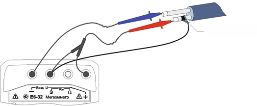
Figure 3. Protective ring connection

Figure 4. Connecting to a transformer
In the first case, a protective ring is used (a piece of foil, bare wire, etc., painted in black in the figure) dressed on the insulator of one of the conductors, in the second case, the body (as an option, the core) of the transformer is shielded. When measuring insulation resistance above 10 GΩ, it is also recommended to use a shielded test cable.
When using a shielded measuring cable, it is necessary to periodically check electrical resistance between the signal and screen plugs. The resistance must be at least 3 GΩ at a test voltage of 2500 V.
4. Turn on the device
5. Use the "Mode" button to select the required test voltage.
6. Press the button twice to start measurements. Rx » Then take measurements within the set time. It should be borne in mind that the established readings are reliable.
To stop the measurement early, press the button « Rx ". The results of the measurement are displayed on the screen for 20 seconds. After that, the megohmmeter switches to the voltage measurement mode.
For short-term measurements, press and hold the " Rx ". Releasing the button stops the measurement.
At the end of the measurement, the removal of residual voltage from the object automatically begins, the current value of which is displayed on the indicator: U n" - the measured voltage on the object.
7.Estimate the measurement error.
5.3.2 Calculation of absorption and polarization coefficients.
The absorption coefficient (KABS) is used to evaluate the degree of wetting of the insulation cable lines, transformers, electric motors, etc.: the charge rate of the absorption capacity (capacitance caused by inhomogeneities and contamination of the material, inclusions of air and moisture) of the insulation is estimated when the test voltage is applied. The absorption coefficient is automatically calculated from the insulation resistance measurement after 15 seconds ( R 15) and 60 seconds (R 60) after the start of the measurement:
TO ABS = R 60/ R 15
The state of insulation is considered excellent if K ABS > 1.6 (there was a long process of charging the absorption capacity with low currents), dangerous - if K ABS<1.3 (происходил кратковременный процесс заряда абсорбционной емкости большими токами) в диапазоне температур от 10 ºС до 30 ºС. В последнем случае, а также при снижении коэффициента абсорбции более чем на 20% относительно заводских данных, рекомендуется сушка изоляции.
To display the absorption coefficient during or at the end of the measurement, press the "Menu Display" button

Figure 5. Insulation resistance measurement result. (Display option with absorption coefficient)
The polarization coefficient (POL) is used to assess the degree of aging of the insulation of cable lines, expensive transformers and electric motors. It takes into account the change in the structure of the dielectric and, as a consequence, the increase in the ability of charged particles and dipoles to move under the action of an electric field. The KPOL coefficient is automatically calculated from the results of measuring the insulation resistance after 60 seconds ( R 60) and 600 seconds (R 600) after the start of the measurement:
K floor = R 600 / R 60
KPOL<1 - ресурс изоляции исчерпан, начинается процесс снижения сопротивления изоляции (возможно, до неприемлемого уровня);
1<КПОЛ<2 - ресурс изоляции снижен, но дальнейшая эксплуатация возможна;
2<КПОЛ<4 - ресурс изоляции достаточен, нет ограничений на эксплуатацию; КПОЛ>4 - the insulation resource is not reduced, there are no restrictions on operation.
Note - The decision on the operation of the insulator with K FLOOR<1 должно приниматься на основе дополнительных исследований: более частые проверки состояния изоляции, прогнозирование момента уменьшения сопротивления до неприемлемого уровня.
To calculate and display the polarization coefficient, it is necessary to set the “To polarization” mode in the menu and, by pressing the “Menu” button, set the appropriate display option.
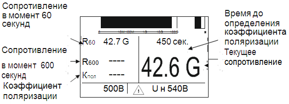
Figure 6. Insulation resistance measurement result (display option with polarization coefficient)
Note 1 - If the measurement time was not sufficient to calculate the absorption or polarization coefficients, then dashes are put in the corresponding paragraphs.
Note 2 - When taking measurements on a number of objects, pay attention to the following:
- if one of the contacts of the measured resistance is grounded, then to it
be different, and it is necessary to find out in advance. The polarity of the test voltage is indicated on the sockets of the megohmmeter.
- induced DC voltage may be present on the object. In this case, it is recommended to carry out measurements twice - with a change in the polarity of the applied test voltage. This will determine the true value of the insulation resistance as the average of the two measurements.
Attention!After each measurement, it is necessary to remove the capacitive charge by short-term grounding of the parts of the object under test, to which the output voltage of the megohmmeter was applied.
6. PRESENTATION OF THE RESULTS OF MEASUREMENTS
According to the results of insulation resistance measurement by specialists electrical laboratories LLC "Energo Alliance" draws up a protocol.
Page 3 of 58
1.3. Checking the isolation of the secondary circuits
According to GOST, to assess the quality of insulation of electrical circuits of equipment, its electrical strength is checked with measurement of insulation resistance before and after testing with increased voltage.
Dielectric strength and insulation resistance are tested between electrically unconnected circuits; between electrical circuits that are connected during the operation of the equipment; between
electrical circuits and metal non-current-carrying parts of the equipment (case).
In the factory documentation for specific equipment, electrical circuits are indicated, the insulation of which should be tested, or the points of application of the test voltage and the connection of measuring instruments.
When checking the resistance and strength of electrical insulation, electronic circuits containing semiconductor devices and microcircuits should be turned off. It is allowed to disconnect, unsolder or shunt elements whose test voltage is lower than the set one. This condition should be specified in the documentation. Re-soldering points must be checked for reliability, for the absence of burrs and other soldering defects. Insulation resistance is measured with special measuring instruments with a measurement error of no more than ± 20%, in some cases it is allowed to measure the insulation resistance using the voltmeter-ammeter method.
The measuring device is selected depending on the insulation resistance values specified in the standards and documentation for specific equipment. The isolation of circuits of equipment containing semiconductor devices is carried out twice with different polarity of the measurement voltage.
The instrument readings are counted 1 min after the measuring voltage is applied to the equipment; The equipment is considered to have passed the test if the measured insulation resistance values are equal to or greater than those specified in the documentation.
Measurement of insulation resistance, as a rule, is carried out with megohmmeters of various types and designs. The main elements of megohmmeters of types Ml 101 and MS-05 are a manually operated DC generator, a measuring device - a DC magnetoelectric ratiometer and additional resistors.
The Ml 101 type megohmmeter has three versions, differing in output voltage and the highest value of the measured resistance: 100 V -100 MΩ, 500 V -500 MΩ, 1000 V - 1000 MΩ, the technical data of the device are given in Table. 1.8.
Table 1.8. Technical data of megohmmeters type M1101
Instrument version |
Measurement limits |
Working part of the scale |
Rated output voltage. AT |
||
The MS-05 type megohmmeter for a voltage of 2500 V has three measurement limits, the technical data of the device are given in Table. 1.9.
When measuring with a megohmmeter, the generator handle must be rotated at a nominal frequency of 120 rpm. At rated speed, the rated voltage is generated at the open terminals of the device. Dependences of the output voltage of megohmmeters
Table 1.9. Technical data of megohmmeter MS-05
from the measured resistance are shown in fig. 1.15, 1.16 (where U is the voltage at the measured resistance as a percentage of the nominal; R is the measured resistance as a percentage of the final value of the working part of the scale).
Before measurement, check the serviceability of the device. For megohmmeters of the Ml 101 type, with the position of the limit switch "LSh" and the rotation of the handle at the rated frequency with the terminals open, the arrow
Rice. 1.15. Load characteristics of the Ml 101 series megohmmeter Fig. 1.16. Load characteristic of megohmmeter type MS-05
megaohmmeter should be set at the oo mark of the MQ scale. With the position of the kQ limit switch and open outputs, the arrow of the ratiometer, when the handle is rotated, should be set at the mark oo of the lower measuring scale Ш, when the output terminals of the device are shorted, in both cases the arrow is set to zero of the corresponding scale.
For megohmmeters of the MS-05 type, when the handle is rotated at a nominal frequency and the terminals are open, the arrow of the device should be set at oo; with closed conclusions JI (line) and 3 (ground), the arrow should be set at 0 on the scale.
Megaohmmeters M4100 / 1-M4100 / 5 - the same type, they have an alternator instead of a DC generator
with rectifier. There are five versions of the device of this type, differing in the parameters of the output voltage and the highest value of the measured resistance, the technical data of the device are given in Table. 1.10.
Table 1.10. Technical data of megohmmeters type M4100
Execution instrument |
Measurement limits |
part of the scale |
|||
M4100/1 M4100/2 M4100/3 M4100/4 M4100/5 |
0-200 |
0-100 |
0-200 |
0,01-20 |
100+10 |
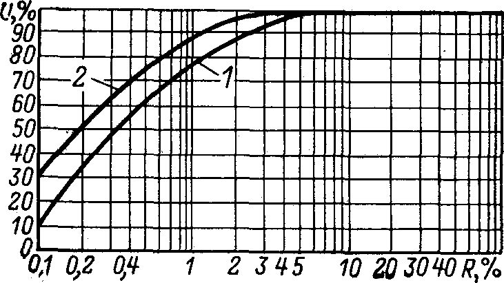
During measurements, the generator handle must be rotated at a nominal frequency of 120 rpm. The dependence of the output voltage of megohmmeters on the measured resistance is shown in fig. 1.17.
Rice. 1.17. Load characteristics of megohmmeters of the M4100 series:
I - M4100/1-M4100/4; 2 - М4100/5
Megaohmmeters M4100/1-M4100/4 have three outputs, designated L (line) (ground) * and the M4100/5 megohmmeter has an additional output E (screen).
* A similar output is designated 3 for other types of instrument.
When measuring the insulation resistance at the A1R limit, the measured resistance is connected to the L-3 terminals, at the kQ limit, a jumper is installed between the L-3 terminals, and the measured resistance is connected to the 3-kQ terminals. Wires included
device, provide the possibility of switching on the outputs without the use of temporary jumpers.
Diagrams for measuring insulation resistance are shown in fig. 1.18
1.19.
The F4100 megohmmeter has an external combined power supply from a 127/220 V network with a frequency of 50 Hz or from a 12 V DC source. The maximum power consumption when powered from a 127/220 V network is 20 V-A, the maximum current consumption from an external DC source is 1 A .
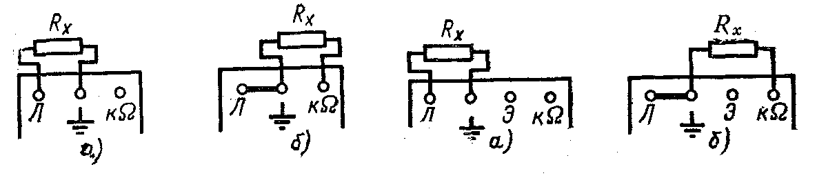
Rice. 1.18. Scheme for measuring insulation resistance with megohmmeters of types M4100 / 1-M4100 / 4:
Rice. 1.19. Scheme for measuring insulation resistance with a megohmmeter type M4100 / 5:
a, - at the limit of MQ; 6 - at the limit / сО
a - at the MQ limit; b - at the limit of KQ
The limits of resistance measurement and the working part of the scale, depending on the position of the switches for the measurement limits, are given in Table. 1.11.
Table 1.11. Technical data of megohmmeter type F4100
Limit Switch Position |
Limits of measurement, MOhm |
Working part of the scale, MOhm |
The rated voltage at the open terminals of the device is 2500 + 250 V, the load characteristic is shown in fig. 1.20. The F4100 megohmmeter consists of the following main functional units: a pulse voltage stabilizer, a voltage converter, a direct current measuring amplifier, a time relay.
When working with the F4100 megohmmeter, additional safety measures must be taken:
before connecting the device to the mains or external DC source, it is reliably grounded. Ground terminal
is located on the front panel of the instrument and is labeled
It must be remembered that a terminal with a similar designation is included in the measuring part of the device circuit and does not have an electrical connection with the terminal for grounding the case;
after releasing the "High voltage" button, the voltage at the output of the megohmmeter (terminals L and E relative to 3) decreases to a safe value in 5-10 s. 
The procedure for working with the F4100 device is indicated in the factory passport and must be strictly followed.
Rice. 1.20. Load characteristics of megohmmeters type F4100:
/ - at the limit of measurement /; 2 - at the limit of measurement II; 3 - at the limit of measurement /I (XJO; X100; X1000)
Megaohmmeters Ф4102/1, Ф4102/2 have a combined power supply from a 220 V network with a frequency of 50 Hz or from built-in chemical current sources with a voltage of 10-14 V. The maximum power consumption when powered from an AC mains is no more than 12 V-A, the maximum current consumption from chemical current sources - no more than 45 A. The resource of the built-in power source under normal conditions of use is at least 250 measurements.
The ranges of measurement of insulation resistance and the value of the voltage at the terminals of the device with an open external circuit are given in Table. 1.12.
Megaohmmeters of this type consist of a converter designed to convert the supply voltage into a constant stabilized voltage of the desired value, and a measuring amplifier with temperature error compensation. Improper installation of chemical current sources can lead to failure of the device.
When measuring insulation, it is necessary to use standard wires included in the manufacturer's delivery set; to replace them, you can use a flexible stranded wire with reinforced insulation (for example, PVL type) and with insulating handles at the ends; safety regulations must be strictly observed.
Table 1.12. Technical data of megohmmeters type F4102
Type of instrument |
Limits of measurement, MOhm |
Ranges of measurement limits, MOhm, with an error |
Rated output voltage, V |
|
Measuring the insulation resistance of the secondary circuits of protection, electrical automation, control is carried out with a megohmmeter for 1000 or 2500 V. When preparing for the measurement, it is necessary to determine the constituent elements, the insulation of which is tested with low voltage, according to the factory documentation, and exclude them from the circuit. To do this, polarized magnetoelectric relays, removable blocks with semiconductor elements, etc. are removed from the blocks. When checking the equipment, it is necessary to remove zener diodes, neon and electronic lamps from the panels so that the currents passing through the lamps do not affect the measurement results; elements that cannot be excluded from the circuit are shorted. For the same purpose, in order to prevent damage to diodes and zener diodes when measuring the insulation resistance of operational control circuits, interlocks and signaling at DC, it is necessary to combine plus and minus with a temporary jumper. When checking, all earth wires installed on this connection must be disconnected. According to the insulation resistance of the conductors of cables, windings, relay contacts with switching drives and all auxiliary devices, they check: in relation to the ground; between phases, conductors, wires, clamps within the same circuit; between electrically unconnected circuits.
The insulation resistance of fully assembled current, voltage, control current, etc. circuits of each connection must be at least 1 MΩ when switched on again.
The insulation resistance of the newly mounted busbars of the operational current and voltage circuits with the descents and cables disconnected from the panels must be at least 10 MΩ. When measuring insulation resistance relative to earth, a wire from terminal 3 is connected to the ground electrode, and a wire from terminal L or Sh is connected to the circuit under test. When measuring insulation between disconnected circuits, the order of connecting the wires does not matter if the circuits do not contain semiconductor elements; in the presence of such elements, the tests are carried out twice with different polarity of the measuring voltage.
Elements designed for a lower level of insulation are tested according to the standards established for them - for example, the insulation of polarized relays is tested with a 500 V megohmmeter. 
Rice. 1.21. High Voltage Insulation Test Diagram
If the results of the insulation resistance measurement are satisfactory, the dielectric strength of the insulation is tested with an applied alternating voltage of 1000 V for 1 min relative to earth. To ensure proper control and safety, test the isolation of all disconnected circuits separately (in series of each group of current transformers, voltage transformers, operational circuits, etc.). At connections, all circuits of which are located within one or two rooms (for example, a control panel - a closed switchgear), it is allowed to test several circuits at once, connected by jumpers made of soft wire with stripped insulation.
From a test device (for example, type IU-65, manufactured by TsLEM Tulenergo), a voltage is applied to the circuits prepared for testing, which is smoothly increased from 0 to 500 V. At this voltage, the leakage current is measured, the condition of the equipment under test, wires, cables, rows of clamps is examined etc. If there are no current surges, sparking and crackling in the circuits, the voltage is raised smoothly to 1000 V and maintained for 1 min with periodic monitoring of the stability of the leakage current. The value of the leakage current is not standardized, since it also depends not only on the insulation resistance, but also on the capacitance of the wires of the secondary circuits relative to the ground. The stability of the leakage current during the tests indicates that there is no reduction in the insulation level. After the test, the voltage is gradually reduced and the test device is disconnected from the mains. In the absence of a special device, you can assemble a circuit from individual devices and devices, as shown in Fig. 1.21. The test transformer T must have a power of at least 200-300 V-A, potentiometers or TUV adjusting transformers are used to regulate the voltage, voltage control is carried out using direct-connected voltmeters on the side of the test voltage. In the absence of a voltmeter with a measurement limit of 1000 V, it is permissible to measure with two voltmeters of the same type when they are switched on in series.
High voltage insulation testing must be carried out in strict compliance with safety regulations.
After completion of the test with increased voltage, a control measurement of the insulation resistance of the tested circuits relative to the ground is carried out with a megohmmeter. The results of control and preliminary measurements should not differ significantly from each other. After completing all work on checking the insulation, it is necessary to remove all temporary jumpers, connect the disconnected devices, devices and connect all ground wires.
Page 1
The insulation resistance of the secondary circuits, measured with a 1000 V megger, must be at least 1 MΩ for each connection. Secondary circuits are tested by applying an AC voltage of 2 kV for 1 minute or by a one-minute insulation test with a 2500 V megohmmeter.
| Scheme for checking the transformation ratio of the current transformer.| Scheme of installation for testing the insulation of secondary circuits with increased voltage. |
The insulation resistance of the secondary circuits relative to earth, measured with a megohmmeter 500 - 1000 V, must be at least 1 MΩ for each connection. By each connection is meant electrically interconnected secondary current circuits or voltage circuits.
The insulation resistance of the secondary circuits is measured in accordance with the method of Ch.
The insulation resistance of the secondary circuits relative to earth, measured with a 500-1000 V megohmmeter, must be at least 1 mg for each connection.
| Scheme for checking the transformation ratio of the current transformer.| Scheme for checking the polarity of the outputs of the current transformer windings. |
The insulation resistance of the secondary circuits relative to earth, measured with a megohmmeter 500 - 1000 V, must be at least 1 MΩ for each connection, which means electrically interconnected secondary current circuits or voltage circuits.
The insulation resistance of the secondary circuits is checked with a megohmmeter with a rated open circuit voltage of at least 1,000 V. During scheduled checks, starting from the second after a new switch-on, it is allowed, instead of testing the dielectric strength of the insulation with an alternating voltage of 1,000 V, to measure the insulation resistance with a megohmmeter with a rated voltage of 2500 V. This assumption is based on the fact that the permissible lower limit of the insulation resistance of the secondary circuits is set to 1 MΩ. When measuring such resistance, a 2500 V megohmmeter, for example, type MS-06, gives an output voltage of about 1,300 V, and this voltage is sufficient to check the dielectric strength of the insulation.
The insulation resistance value of the secondary circuits must be at least: 10 Mohm for DC buses and voltage on the control panel; 1 Mohm for each connection of secondary circuits and power circuits; 1 Mohm for control, protection and excitation circuits of DC electric machines. To measure the insulation resistance of DC busbars, it is necessary to turn off the fuses or the circuit breaker on the supply side and the fuses of all outgoing connections; connect a megger between the negative bus and ground and measure the insulation resistance. Then reconnect the megger and check the insulation resistance of the positive bus.
Measurement of insulation resistance of secondary control, protection, automation and signaling circuits is carried out together with a 1000 V megohmmeter installed in these circuits and equipment.
If the insulation resistance of the secondary circuits is less than the norm (Table 14), then tests of the secondary circuits with an increased voltage of the industrial frequency of 1000 V are mandatory. Secondary circuits with an operating voltage of 60 V and less are not subjected to increased voltage tests.
To measure the insulation resistance of secondary circuits with voltages not higher than 24 - 48 V, megohmmeters should be used only for voltages not higher than 500 V, and in other cases - for 500 and 1000 V.
Only periodic measurements of the insulation resistance of secondary circuits and devices, provided that they are made with the same megohmmeters and under the same environmental conditions, make it possible to establish reliable criteria for the state of their insulation. If even with a low insulation resistance it does not change over time, then we can conclude that this secondary device or circuit is suitable for further work. If, on the other hand, the insulation resistance decreases continuously and noticeably, then, despite the good insulation IB considered, it should be considered that such insulation will not be able to provide normal operating conditions for this secondary device and therefore measures must be taken to improve it.
Only periodic measurements of the insulation resistance of secondary circuits and devices, provided that they are made with the same megohmmeters and under the same environmental conditions, make it possible to establish reliable criteria for the state of their insulation.
If, when measuring the insulation resistance of secondary circuits, it turns out to be lower than the specified values due to contamination, dampness or breakdown, then before putting into operation, work must be carried out to increase the insulation resistance to normal. Such works include drying, cleaning from dust and dirt, replacement of individual defective conductors of the control cable, relays, clamps, linings and other elements.