General instructions and order of installation of counters:
Meters can only be used for stationary installation in closed, easily accessible rooms that do not have aggressive vapors and gases.
It is necessary to mount the meters on walls or shields that are not subject to vibration. The recommended height from the floor is 1.4 - 1.7 m.
In rooms where contamination and mechanical damage are possible, meters are installed in safety cabinets.
Fix the meter with three screws (deviation from the vertical position is not more than 1°).
It is necessary to turn on the meters in full accordance with their nominal data and the marking of the windings, which is available both on the terminal box and on the diagram located on the inside of the terminal box cover, and also observe the specified phase sequence (the meter connection diagram is given below).
During installation, it is necessary to especially ensure reliable contact of the connected wires and connections between the series and parallel circuits of the meter (in the terminal box).
Installation, dismantling, repair, verification and branding of the meter should be carried out only by specially authorized organizations and persons.
For transformer meters, on an additional shield attached to the front side of the cover of the terminal block of the meter, when the meter is put into operation, the transformation ratios for current and (or) voltage are applied instrument transformers, complete with which the meter must work, and also the coefficient K \u003d Knapr * Kcurrent is applied, equal to the product of the coefficients of the measuring voltage and current transformers, by which the readings of the counting mechanism must be multiplied in order to obtain the true electricity metered. When only current transformers are used, the voltage coefficient Knapr = 1. The application of the coefficients and the sealing of the cover is carried out by organizations and persons authorized to do so.
Counters reactive energy are made with a backstop. At the request of the customer, active energy meters can be manufactured with a stopper. The presence of a backstop on the counter is indicated on the plate of the counting mechanism according to GOST 25372-95.
The meter label shows the nominal and maximum currents meter, for example: 10 - 40A, where 10A - nominal, 40A - maximum meter currents. For transformer meters, only the rated current is indicated.
The presence of indications on the counting mechanism at the time of purchase is a consequence of the adjustment and verification of the counter at the factory, and not evidence of its operation.
To not allow short circuits in the network, current overloads above 200% of the nominal for transformer meters, and for direct connection meters - current values \u200b\u200bhigher than the maximum indicated on the shield. Violations lead to the appearance of an additional error, and significant ones - to the failure of the meter.
Do not place foreign objects on the meter, hit or throw the meter.
During the verification, installation and operation of the meter, the requirements of the "Safety Rules for the Operation of Consumer Electrical Installations" must be observed.
Scheme of direct connection of the meter
Meter connection diagram using two current transformers
Meter connection diagram using three current transformers
According to the requirements of the rules for electrical installations: "newly installed single-phase meters must have fillings
state verification with a prescription of no more than 2 years, and on three-phase meters - with a prescription of no more than 12 months.
First of all, this indicates that the electric meter you are purchasing should already have two seals (one seal can be installed on the electronic meter). You should check the presence of these seals. They are often placed on the screws that secure the casing of the electric meter, and there are two types: external or internal. External seals are made of lead, less often of plastic, clamped on a wire threaded through a screw or eyelet. 
Internal seals are black or red mastic poured into the screw recess, sometimes covered with silver. 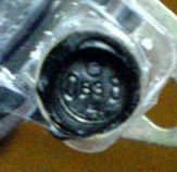
All seals must have a clear impression and not have mechanical damage, which should be paid special attention to when buying. A duplicate of the state verifier's imprint in the form of a seal is usually affixed to the last pages of the electric meter's passport. 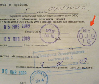
On the print of the seals, the year of verification of the electric meter is indicated, or rather the last two digits of the year and the attributes of the state verifier on a small scale between the digits. On seals of external execution, to all this, on the reverse side, the quarter of the year of verification, printed in Roman numerals, is added. Therefore, after looking at the year of verification of the meter on the seals, you need to make sure that it is not expired, that is, no more than two years have passed for a single-phase meter and no more than 12 months for a three-phase one.
It also often happens that two seals are installed on the meter, but one has an imprint of the state verifier, and the other has an imprint of the manufacturer's quality control department, which is considered quite acceptable. But if both seals have an OTK imprint, or it’s not at all clear which one, then you should not buy such an electric meter, because before you install it, you will have to take it to the standardization and metrology center for verification and pay additional money accordingly. You will have to do the same if you buy a meter with expired state verifier seals. That's all for fillings.
Hi all! Today's article will be devoted to installation and connection three-phase meter direct connection. A little theory will be given, a switching circuit, instructions for a three-phase meter, and, as usual, a lot of photos.
In principle, if a three-phase meter is directly connected, then its installation is not much different from the installation of a single-phase meter. I have already written about this on SamElectrica more than once - and.
And if you are interested at all, subscribe to receive new articles and join group in VK !
You can familiarize yourself with how a three-phase system works, and we move on to the practical installation of a three-phase meter.
Transformer switching circuits are used at currents of more than 100 A per phase, and in this article we will consider only direct connection meters.
Installation and connection of a three-phase direct connection meter
Here I will give a practical case when I happened to change a three-phase meter in one of the organizations of Taganrog.
Organizational moments of meter replacement
1. It is necessary to find out why the counter is changing. In my case, there was an Energonadzor order, this official document is enough.
2. At what time we change. It is important to agree on what time we turn off the electricity, and how long it will take. In my case it's a design firm with a lot of computers and creative people, and inspiration can fly away through my fault ;). In addition, it is desirable that it be daylight hours, which is quite logical even with a flashlight.
3. How to remove phases for replacement. In the simplest case, like mine, in front of the counter is circuit breaker, and relieve stress - a second of business. But sometimes it is necessary:
- look for the keys to the basement
- look for and negotiate with a local electrician
- find out which group in the RP my consumer hangs on
- eliminate the moral problems of people who are turned off along the way
You can, of course, replace a three-phase meter in the way that is often done with - work under voltage. But here it is very, very dangerous, even more dangerous than.
Often in such cases I joke that electricians do not have to jump from a parachute - there is enough adrenaline already.
Removing the old counter
Why it had to be changed is not important, but an order was issued in which it was said that the meter should be of the 1st accuracy class. In addition, the Energomer counter was originally installed, and I decided to install the same one in order to less bother with fasteners during installation. What came of it, read on.
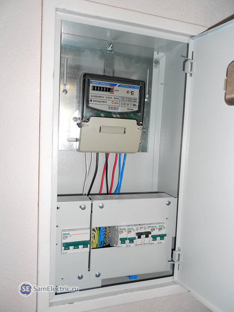
This is what the electrical panel looked like with the old three-phase meter before replacing it:

An introductory machine is visible at the bottom left, which made it easy to turn off the power to the meter, and change it calmly. However, do not relax! There is voltage (380V) in the shield at the input (usually upper) terminals of the machine.
If you zoom in on the next photo, you can see that the counter is not so old - 2010. But again, let's not get into that.

We remove the seal and the cover covering the terminals:

The installation site of the counter after dismantling the old one looks like this:

Installation of a new meter
It was not possible to buy exactly such a meter, I purchased Energomer TsE6803V Sh M7 R32. How this name is deciphered - see the instructions that can be downloaded below.

The back counter looks like this:

Connecting a new meter
With the connection, not everything went smoothly, although the old and new counters- one manufacturer (Energomer), and at first glance, they are similar in design. How it works single phase meter Energomer - in my other article. Three-phase is arranged in the same way, somehow I will publish an article with a photo.
As you can see in the photo below, the meter is mounted on a DIN rail. However, the kit comes with a bracket for attaching to the shield. I figured this out before buying, hoping that there would be no problems during installation. But when comparing meters of the same model, it turned out that not everything is so simple for Russian manufacturers.
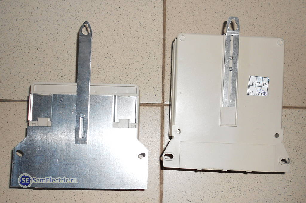
7 Difference in fixing, new - on the left (meters lie on the tiled floor)
The counters are arranged so that the side openings are at the same level. The goal was to get into the same mounting holes. At the same time, the Vertical bar had to be lowered as much as possible down, and only then all three holes coincided. But the terminals of the counter as a result dropped by about 2-3 cm.
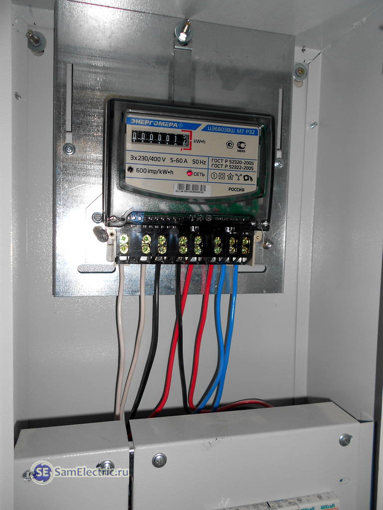
8 New three-phase meter installed and connected
I had to lower the wires down, slightly pushing them vertically down. The meter connection diagram is given below, but what happened in the end:
9 Installation completed
Wiring diagram of a three-phase direct connection meter
The diagram is given in the instructions, and below is a diagram that shows as close to reality as possible what and where to connect.

Wiring diagram of a three-phase meter
Features of connecting three-phase meters of direct connection
Three-phase meters of direct connection, as a rule, are switched on for a total load of up to 50 kW. But if at the same time three-phase consumers - motors - are not used (or little used), then you need to make sure that there is no large phase imbalance.
That is, so that the load currents in phases do not differ by more than 20%. In practice, of course, this is difficult to achieve, but it is necessary to strive for this. At the design stage, and at the stage of operation and alteration of electrical wiring. There are two reasons.
When one phase will work to the fullest (wires, contacts heat up, reliability decreases), then the other one rests.
The accuracy of the meter readings is reduced (this applies to old, inductive models).
When replacing any counter, you need to remember one more thing. Be sure to check the broach of the contacts in the electrical panel, especially BEFORE the meter.
For example, in my case, when I pressed the wires down, one of them literally jumped out of the introductory machine. I was shocked. Apparently, a small current flowed through this phase, since the wire was in order. And if more - heat, smoke, sparks ...
In fact, there are more subtleties, but you can’t describe everything, you will put it yourself - you will encounter it, write comments.
Instructions for a three-phase direct connection meter
Below is the instruction manual - in the form of pictures and in the form of a file that can be downloaded free of charge and freely, like everything on SamElectrica.


Download the instruction manual for the Energomer three-phase meter:
• / Designation, parameters, connection diagram of a three-phase direct connection meter, pdf, 2 MB, downloaded: 901 times./
Another photo of the shield with a three-phase meter
I also changed the counter, I post a photo - it’s interesting from the point of view of installation.


If previously three-phase meters were most often used in production, then at present they are also used in everyday life. This is due both to the ubiquitous distribution of various three-phase machines, and the increase in power consumption in single-phase network.
Three-phase induction electric meter
Metering devices
With an increase in the number electrical appliances power consumption in everyday life has increased significantly and began to exceed 15 kW per apartment or house, and according to GOST, this already requires power from a three-phase network.
If you turn on the load with a power of 15 kW in a single-phase network, a current of more than 70A flows through one supply wire, the cable cross section is 10mm 2. If this power is supplied in three phases, then the current in the cable will be less than 25A, and the cable cross section will be 2.5 mm 2. The table below is proof of this. With the same power of a correctly made direct three-phase connection it is permissible to significantly reduce the cable cross-section, since the load will be distributed into 3 phases, and the current strength in each of them will be much lower. Reducing the cable cross-section not only reduces the cost of wiring in a private house, but also simplifies its installation.
| Copper conductors of wires and cables | ||||
|---|---|---|---|---|
| Conductor cross section, mm. | Voltage, 220 V | Voltage, 380 V | ||
| current, A | power, kWt. | current, A | power, kWt. | |
| 1.5 | 19 | 4.1 | 16 | 10.5 |
| 2.5 | 27 | 5.9 | 25 | 16.5 |
| 4 | 38 | 8.3 | 30 | 19.8 |
| 6 | 46 | 10.1 | 40 | 26.4 |
| 10 | 70 | 15.4 | 50 | 33 |
| 16 | 85 | 18.7 | 75 | 49.5 |
| 25 | 115 | 25.3 | 90 | 59.4 |
| 35 | 135 | 29.7 | 115 | 75.9 |
| 50 | 175 | 38.5 | 145 | 95.7 |
| 70 | 215 | 47.3 | 180 | 118.8 |
| 95 | 260 | 57.2 | 220 | 145.2 |
| 120 | 300 | 66 | 260 | 171.6 |
Connections
- three-wire - for a network without a neutral wire;
- four-wire - with a neutral wire.
The connection of a three-phase meter should be carried out taking into account the following feature: devices can be connected both directly to the network and through current transformers. It depends on the current strength in the network: up to 100A - direct connection is allowed, above - through a transformer.
Three-phase meters also differ in the way they are connected to the network:
- direct (direct) inclusion;
- semi-indirect mounting (via current transformer);
- indirect (using current and voltage transformers) inclusion.
Direct connection
Such an installation of a three-phase electric meter Energomer or other equipment in a private house does not differ from a single-phase circuit. All consumed energy passes directly through one device. The figure below shows a diagram of a direct (direct connection) three-phase meter. The disadvantage of this inclusion is the power limitation - no more than 60 kW.

Scheme of direct connection of a three-phase meter
Electricity meters of indirect connection in household power supply are not used, because they are intended for electricity metering only for high-voltage industrial networks of 6 (10) kV.
Meters also differ in the type of measured energy: active and reactive energy meters.
Semi-indirect inclusion
With this connection, Energomer's metering devices are switched on through current transformers. Such installation of the circuit allows you to keep a record of electricity with significantly large capacities online. However, it requires taking into account the transformation ratio, which complicates the calculation of the cost. The disadvantage of this type of inclusion is the difficulty of checking meter readings for power supply organizations.

Scheme of semi-indirect inclusion of a three-phase meter
In the figure, L1 and L2 are the inputs and outputs of the corresponding phases, I1 and I2 are the measuring windings.
Counter types
induction
The principle of operation of this type of electricity meter is based on the occurrence of a torque in the disk under the action of an alternating magnetic field. The figure below schematically shows the device of a single-phase induction meter Energomer.
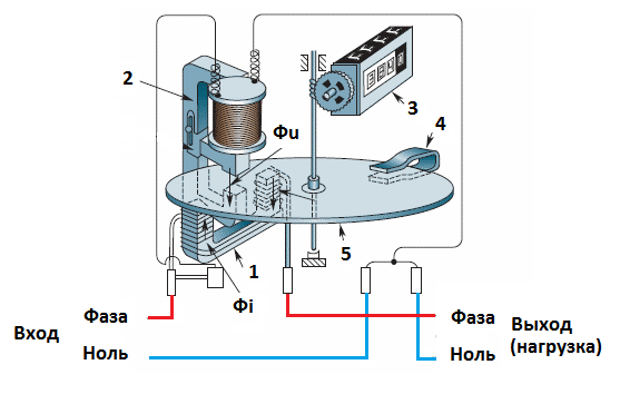
The design of a single-phase induction meter
1 - current coil, the consumed current flows through it, a magnetic flux Фi arises in it, which penetrates the aluminum disk, causing the appearance of an eddy current in it. This current, in turn, forms a magnetic field, it interacts with magnetic field Fu voltage coils 2.
The interaction of these fields sets the aluminum disk in motion, it sets the mechanical counter 3 through the worm gear.
4 – permanent magnet, it creates a decelerating magnetic field in a rotating disk. The equality of the rotating and retarding fields gives the disk rotational stability. The speed of rotation of the disk depends on the strength of the current flowing through the counter through the current coil.
The principle of operation of a three-phase induction meter Energomer is the same. The difference is that it has another aluminum disk installed. The figure below shows the device of such an electricity meter.

Three-phase induction meter
Currently, there is an active replacement of induction meters with electronic ones, there are several reasons for this:
- insufficient accuracy of induction meters;
- the complexity of their application for accounting in a multi-tariff mode;
- inability to use in automatic accounting systems.
Electronic
The principle of operation of these counters is based on counting the pulses generated by the ADC (analogue-to-digital converter), the number of which is strictly proportional to the current flowing through the circuit. The block diagram shows the interaction of individual meter nodes.
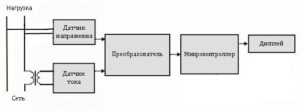
Block diagram of an electronic meter
Voltage and current sensors installed in the meter receive network parameters and transmit them in analog form to the converter. It generates rectangular counting pulses (digital form), the frequency of which depends on the received data, and transmits them to the microcontroller, where they are processed, stored and displayed. This is the general logic of the electronic counter.
An electronic meter is connected to the network according to the same schemes as induction meters.
Advantages:
- reliability and accuracy (accuracy classes 0.2 to 2.0);
- wide operating temperature range (from -40 to +60);
- easily integrated into the system of remote automatic accounting;
- the possibility of accounting for multi-tariff zones.
Flaws:
- high sensitivity to industrial noise;
- high demands on the quality of electricity (power surges);
- relatively high price (although recently there has been a slight downward trend)
- practically beyond repair.
Installation of metering devices
When installing the meter (regardless of the scheme), you should be guided by the "Electrical Installation Rules" (PUE).
When installing a meter in an apartment building, there are practically no options; electrical panels are provided for them on the landing, so there is no need to look for a place.
In private households, there are several options:
- installation in the house;
- installation on the outer wall of the house;
- support installation.
Although these installation options are taken from the PUE, it is also said there that “meters should be installed in dry rooms, a place not cramped for work, and with a temperature of winter time not lower than 0". It is allowed to connect a three-phase electric meter in sealed cabinets on the outer wall of the house or on a support. Properly executed installation of the circuit assumes that in winter time heating to positive temperature should be provided at the expense of the consumer.
Often, the energy supply organization insists on installation outside the home, arguing that it provides free access for their employees to take readings, but then one such meter is in no way protected from unauthorized persons, petty hooligans, vandals.
When operating a modern transformer electronic meter, readings can be correctly taken remotely, through appropriate means of communication. So providing direct access to the metering device may be required only in order to check the integrity of the seal.
For the integrity of the meter (meter), all responsibility rests with the consumer. If the power supply organization insists on an outdoor installation, then it can be required to draw up an agreement on the delimitation of liability, otherwise if the meter is damaged by vandals, the consumer will repair the damaged equipment at his own expense and pay a fine.
The figure shows an electricity metering cabinet for indoor installation.
![]()
Electricity metering cabinet
The metering cabinet can be combined with a cabinet for installing protective switches. It will be correct to use electrical shield with the installation of a meter in it, all automatic and differential switches and SPE.
Modern consumer electronics (including meters) are very sensitive to short-term impulse overvoltage. For guard household appliances and networks in the circuit, you can include a surge voltage limiter (SPE). impulse voltage may occur from a lightning strike into the line, from switching loads, for example, turning on / off powerful engines, etc. That is why it is recommended to install SPE as effective remedy protection.
When installing a direct meter, an introductory shutdown device is also installed with it - batch switch, which allows you to turn it off for replacement. Often, power engineers also seal this device in order to avoid unauthorized disconnection by the consumer through it.
If a wardrobe is installed in the house, then it must also be securely locked to prevent free access, especially for children. SPE allows you to achieve this result.
Connection. Video
How to connect the meter and shield with your own hands, you can learn from this video.
Installing the meter is not a very complicated operation, but it is more rational for employees to carry it out energy supply organization or professionals certified to carry out this work.