To convert the voltage of one level to the voltage of another level is often used pulse voltage converters using inductive energy storage. Such converters are characterized by high efficiency, sometimes reaching 95%, and have the ability to obtain increased, reduced or inverted output voltage.
In accordance with this, three types of converter circuits are known: step-down (Fig. 4.1), step-up (Fig. 4.2) and inverting (Fig. 4.3).
Five elements are common to all these types of converters: a power source, a key switching element, an inductive energy storage device (an inductor, a choke), a blocking diode, and a filter capacitor connected in parallel with the load resistance.
The inclusion of these five elements in various combinations allows you to implement any of the three types of pulse converters.
The output voltage level of the converter is controlled by changing the width of the pulses that control the operation of the key switching element and, accordingly, the energy stored in the inductive storage device.
The output voltage is stabilized by using feedback: when the output voltage changes, the pulse width changes automatically.
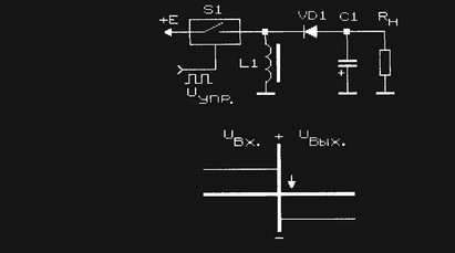
The buck converter (Fig. 4.1) contains a series-connected circuit of a switching element S1, an inductive energy storage L1, a load resistance Rn and a filter capacitor connected in parallel to it C1. The blocking diode VD1 is connected between the connection point of the key S1 with the energy storage L1 and a common wire.
Rice. 4.1. The principle of operation of the step-down voltage converter

Rice. 4.2. The principle of operation of the step-up voltage converter
When the key is open, the diode is closed, the energy from the power source is stored in the inductive energy storage. After the key S1 is closed (opened), the energy stored by the inductive storage L1 is transferred through the diode VD1 to the load resistance R n. Capacitor C1 smooths out the voltage ripple.
The step-up pulse voltage converter (Fig. 4.2) is made on the same basic elements, but has a different combination of them: a series circuit of an inductive energy storage device L1, a diode VD1 and a load resistance with a filter capacitor connected in parallel C1 is connected to the power source. The switching element S1 is connected between the connection point of the energy storage device L1 with the diode VD1 and the common bus.
When the switch is open, the current from the power source flows through the inductor, in which energy is stored. Diode VD1 is closed, the load circuit is disconnected from the power source, key and energy storage. The voltage on the load resistance is maintained due to the energy stored on the filter capacitor. When the key is opened, the self-induction EMF is added to the supply voltage, the stored energy is transferred to the load through the open diode VD1. The output voltage obtained in this way exceeds the supply voltage.
Rice. 4.3. Pulse voltage conversion with inversion
The pulse-type inverting converter contains the same combination of basic elements, but again in a different connection (Fig. 4.3): a series circuit of a switching element S1, a diode VD1 and a load resistance R n with a filter capacitor C1 is connected to the power source. The inductive energy storage L1 is connected between the connection point of the switching element S1 with the diode VD1 and the common bus.
The converter works like this: when the key is closed, energy is stored in an inductive storage device. Diode VD1 is closed and does not pass current from the power source to the load. When the switch is turned off, the self-induction EMF of the energy storage device is applied to the rectifier containing the diode VD1, the load resistance R n and the filter capacitor C1. Since the rectifier diode passes only negative voltage pulses into the load, a negative sign voltage is formed at the output of the device (inverse, opposite in sign to the supply voltage).
To stabilize the output voltage switching regulators of any type conventional "linear" regulators can be used, but they have low efficiency. In this regard, it is much more logical to use pulse voltage stabilizers to stabilize the output voltage of pulse converters, especially since such stabilization is not difficult at all.
Switching voltage stabilizers, in turn, are divided into Pulse Width Modulated Stabilizers and on stabilizers with frequency-pulse modulation. In the first of them, the duration of the control pulses changes at a constant frequency of their repetition. Secondly, on the contrary, the frequency of the control pulses changes with their duration unchanged. There are impulse stabilizers with mixed regulation.
Below, amateur radio examples of the evolutionary development of pulse converters and voltage stabilizers will be considered.
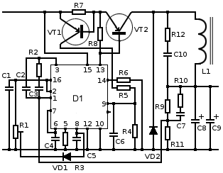
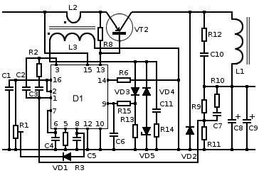
The master oscillator (Fig. 4.4) of pulse converters with unstabilized output voltage (Fig. 4.5, 4.6) on the KR1006VI1 (NE 555) chip operates at a frequency of 65 kHz. The output rectangular pulses of the generator are fed through RC circuits to transistor key elements connected in parallel.
The inductor L1 is made on a ferrite ring with an outer diameter of 10 mm and a magnetic permeability of 2000. Its inductance is 0.6 mH. Coefficient useful action converter reaches 82%. The output ripple amplitude does not exceed 42 mV and depends on the capacitance value
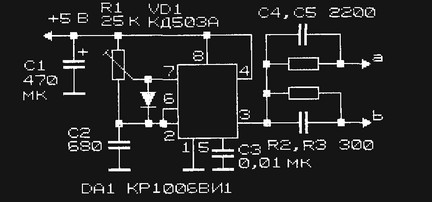
Rice. 4.4. Driving oscillator circuit for pulse voltage converters
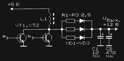
Rice. 4.5. Scheme of the power part of the step-up pulse voltage converter +5/12 V

Rice. 4.6. Scheme of an inverting pulse voltage converter +5 / -12 V
capacitors at the output of the device. The maximum load current of devices (Fig. 4.5, 4.6) is 140 mA.
The rectifier of the converter (Fig. 4.5, 4.6) used parallel connection low-current high-frequency diodes connected in series with equalizing resistors R1 - R3. This entire assembly can be replaced by one modern diode, designed for a current of more than 200 mA at a frequency of up to 100 kHz and a reverse voltage of at least 30 V (for example, KD204, KD226). As VT1 and VT2, it is possible to use transistors of the KT81x type: n-p-n structures- KT815, KT817 (Fig. 4.5) and p-n-p - KT814, KT816 (Fig. 4.6) and others. To improve the reliability of the converter, it is recommended to connect a diode of the KD204, KD226 type in parallel with the emitter-collector junction of the transistor so that it is closed for direct current.
However, the price of such a device medium power(300-500 W) is several thousand rubles, and the reliability of many Chinese inverters is quite controversial. DIY manufacturing simple converter- this is not only a way to significantly save money, but also an opportunity to improve your knowledge in electronics. In case of failure, the repair of a home-made circuit will be significantly easier.
Common Schemes
Simple pulse converter
The circuit of this device is very simple., and most of the details can be extracted from unnecessary . Of course, it also has a noticeable drawback - the voltage of 220 volts obtained at the output of the transformer is far from sinusoidal in shape and has a frequency much higher than the accepted 50 Hz. Do not connect electric motors or sensitive electronics directly to it.

In order to be able to connect to this inverter containing impulse blocks power supply equipment (for example, a laptop power supply), an interesting solution was applied - a rectifier with smoothing capacitors is installed at the output of the transformer. True, the connected adapter can work only in one position of the outlet, when the polarity of the output voltage matches the direction of the rectifier built into the adapter. Simple consumers such as incandescent lamps or a soldering iron can be connected directly to the output of the TR1 transformer.
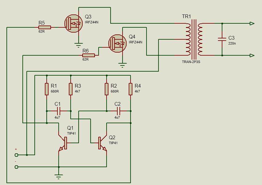
The basis of the above circuit is the TL494 PWM controller, the most common in such devices. The frequency of the converter is set by the resistor R1 and the capacitor C2, their ratings can be taken slightly different from those indicated without a noticeable change in the operation of the circuit.
For greater efficiency, the converter circuit includes two arms on power field-effect transistors Q1 and Q2. These transistors must be placed on aluminum heatsinks, if you intend to use a common heatsink, install the transistors through insulating gaskets. Instead of those indicated on the IRFZ44 diagram, you can use IRFZ46 or IRFZ48 close in parameters.
The output inductor is wound on a ferrite ring from the inductor, also removed from. The primary winding is wound with a wire with a diameter of 0.6 mm and has 10 turns with a tap from the middle. A secondary winding containing 80 turns is wound on top of it. You can also take the output transformer from a broken uninterruptible power supply.
Instead of high-frequency diodes D1 and D2, you can take diodes of types FR107, FR207.
Since the circuit is very simple, after switching on, with proper installation, it will start working immediately and will not require any configuration. It will be able to deliver current up to 2.5 A to the load, but the optimal mode of operation will be a current of no more than 1.5 A - and this is more than 300 W of power.
Ready-made inverter of such power would cost about three or four thousand rubles.
This scheme is made on domestic components and is quite old, but this does not make it less effective. Its main advantage is the output of a full-fledged alternating current with a voltage of 220 volts and a frequency of 50 Hz.
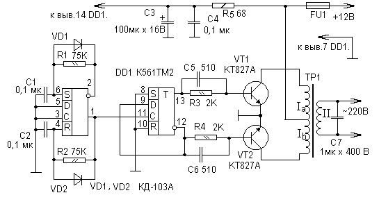
Here, the oscillation generator is made on a K561TM2 chip, which is a dual D-flip-flop. It is a complete analogue of the foreign CD4013 chip and can be replaced by it without changes in the circuit.
The converter also has two power arms on bipolar transistors KT827A. Their main drawback compared to modern field ones is a greater resistance in the open state, which is why they have stronger heating at the same switched power.
Since the inverter operates at low frequency, the transformer must have a powerful steel core. The author of the scheme suggests using the common Soviet network transformer TS-180.
Like other inverters based on simple PWM circuits, this converter has a voltage waveform quite different from the sinusoidal output, but this is somewhat smoothed out by the large inductance of the transformer windings and the output capacitor C7. Also, because of this, the transformer may emit a noticeable hum during operation - this is not a sign of a circuit malfunction.
A simple transistor inverter
This converter works on the same principle as the circuits listed above, but the rectangular pulse generator (multivibrator) in it is built on bipolar transistors.
The peculiarity of this circuit is that it remains operational even on a heavily discharged battery: the input voltage range is 3.5 ... 18 volts. But, since it lacks any stabilization of the output voltage, when the battery is discharged, the voltage at the load will also proportionally drop.
Since this circuit is also low-frequency, a transformer will be required similar to that used in the inverter based on K561TM2.
Inverter Circuit Improvements
The devices presented in the article are extremely simple and for a number of functions can't compare with factory counterparts. To improve their characteristics, you can resort to simple alterations, which, moreover, will allow you to better understand the principles of operation of pulse converters.
Increasing output power
All the described devices work according to the same principle: through the key element (the output transistor of the arm), the primary winding of the transformer is connected to the power input for a time specified by the frequency and duty cycle of the master oscillator. This generates impulses magnetic field, which excite common-mode pulses in the secondary winding of the transformer with a voltage equal to the voltage in the primary winding multiplied by the ratio of the number of turns in the windings.
Therefore, the current flowing through the output transistor is equal to the load current multiplied by the reciprocal of the turns ratio (transformation ratio). Exactly maximum current, which can pass a transistor through itself, and determines the maximum power of the converter.
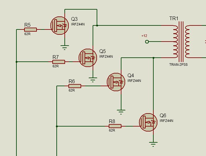
There are two ways to increase the power of the inverter: either use a more powerful transistor, or use a parallel connection of several less powerful transistors in one shoulder. For a home-made converter, the second method is preferable, since it allows not only the use of cheaper parts, but also keeps the converter working if one of the transistors fails. In the absence of built-in overload protection, such a solution will significantly increase the reliability of a home-made device. The heating of transistors will also decrease during their operation at the same load.
On the example of the last scheme, it will look like this:
Automatic shutdown when the battery is low
The absence in the converter circuit of a device that automatically turns it off when the supply voltage drops critically, can seriously let you down, if you leave such an inverter connected to the car battery. Supplementing a homemade inverter with automatic control will be extremely useful.
Protozoa circuit breaker loads can be made from an automotive relay:
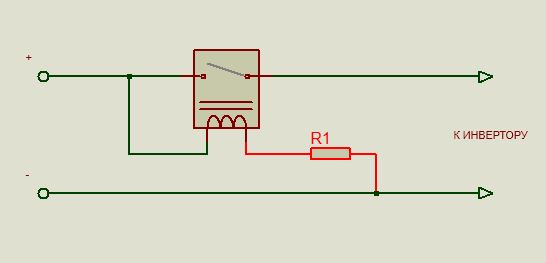
As you know, each relay has a certain voltage at which its contacts close. By selecting the resistance of the resistor R1 (it will be about 10% of the resistance of the relay winding), the moment is set when the relay breaks the contacts and stops supplying current to the inverter.
EXAMPLE: Take a relay with an operating voltage (U p) 9 volts and winding resistance (R o) 330 ohm. To make it work at a voltage above 11 volts (U min), in series with the winding, you need to turn on a resistor with resistanceR n, calculated from the condition of equalityU p /R o =(U min —U p) /R n. In our case, a 73 ohm resistor is required, the nearest standard value is 68 ohm.
Of course, this device is extremely primitive and is more of a workout for the mind. For more stable operation, it must be supplemented with a simple control scheme that maintains the shutdown threshold much more accurately:
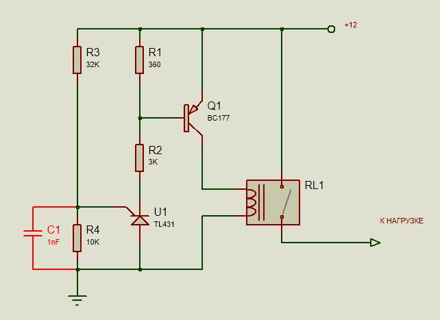
Adjustment of the response threshold is carried out by selecting the resistor R3.
We suggest watching a video on the topic
Inverter Fault Detection
The listed simple circuits have two of the most common faults - either there is no voltage at the output of the transformer, or it is too low.
- The first case is either a simultaneous failure of both arms of the converter, which is unlikely, or a failure of the PWM generator. To check, use an LED probe, which can be purchased at any radio parts store. If the PWM is working, you will see the presence of a signal at the gates of the transistors by the rapid pulsations of the diode glow (this is especially noticeable in low-frequency circuits). If there is a control signal, check for breaks in the transformer connections and the integrity of its winding.
- A large voltage drop is a clear sign of the failure of one of the power arms of the inverter. You can find a failed transistor in the simplest way - its radiator will remain cold. Replacing the key will restore the inverter to work.
Conclusion
As can be understood from the materials of the article, it is not so difficult to make a simple 12-220 volt converter with your own hands.
And, although such devices cannot be compared in terms of a set of additional features or the attractiveness of the appearance with the factory ones, they will cost the owner much cheaper. Subject to the operating rules, a home-made converter will work for a very long time, because in such simple device virtually nothing to break.
Finally, we suggest watching another video about making a device from a computer power supply
DC voltage drop. How a step down converter works. Where does it apply. Description of the operating principle. Step-by-step instruction for design (10+)
Step-down pulse voltage converter. Design. Calculation
For downgrading constant voltage with minimal losses and obtaining a stabilized output, the following approach is applied. The constant voltage is converted into pulses of variable duty cycle. These pulses are then passed through an inductor. Energy is stored in a storage capacitor. Feedback monitors the stability of the output voltage and for this regulates the duty cycle of the pulses.
If there is no need to reduce losses, then a series continuous stabilizer is used.
The principle of operation of a step-down voltage converter is based on the property of an inductor (choke) to accumulate energy. The accumulation of energy is manifested in the fact that the current through the inductor, as it were, has inertia. That is, it cannot change instantly. If a voltage is applied to the coil, then the current will gradually increase; if a reverse voltage is applied, the current will gradually decrease.
To your attention a selection of materials: In the diagram, we see that the control unit D1 depending on the voltage across the capacitor C2 closes and opens the power switch. Moreover, the higher the voltage C2, the shorter the time for which the key closes, that is, the lower the fill factor (the greater the duty cycle). If the voltage across the capacitor C2 exceeds a certain value, then the key generally ceases to close until the voltage drops. How this operation of the control circuit is ensured is described in the article on pulse-width modulation. When the power switch is closed, the current follows the path S1. In this case, a voltage is applied to the inductor, equal to the difference between the input and output voltage. The current through the coil increases in proportion to the voltage applied to the coil and the time for which the switch closes. The coil stores energy. The flowing current charges the capacitor C2. When the power switch is open, the current follows the path S2 through a diode. An output voltage with the opposite sign is applied to the inductor. The current through the coil decreases in proportion to the voltage applied to the coil and the time during which the switch is open. The current flowing still charges the capacitor C2. When the capacitor C2 charged, the key stops closing, the capacitor stops charging. The key will start to close again when the capacitor C2 slightly discharged under load. Capacitor C1 is needed in order to reduce the current ripple in the input circuit, to select from it not a pulsed, but an average current. Advantages, disadvantages, applicabilityEnergy losses directly depend on the ratio of input and output voltages. So a buck converter can theoretically generate a large output current at a low voltage from a small input current but a large voltage, but we have to interrupt high current at high voltage, which guarantees high switching losses. So buck converters are used if the input voltage is 1.5 - 4 times the output voltage, but they try not to use them with a larger difference. We will analyze the process of designing and calculating a step-down converter and test it with examples. At the end of the article there will be a form in which you can fill in the necessary source parameters, conduct an online calculation and get the denominations of all elements. Let's take the following diagrams as an example:
One of the problems of buck converters is the difficulty of controlling the power switch, since its emitter (source) is usually not connected to a common wire. Next, we will consider several options for solving this problem. For now, let's focus on a somewhat non-standard inclusion of a microcircuit - a PWM controller. We use the 1156EU3 chip. In this microcircuit, the output stage is made according to the classical push-pull circuit. The midpoint of this cascade is connected to leg 14, the emitter of the lower arm is connected to a common wire (leg 10), the collector of the upper arm is connected to leg 13. We will connect leg 14 to the common wire through a resistor, and connect leg 13 to the base of the key transistor. When the upper arm of the output stage is open (this corresponds to the supply of a trigger voltage to the output), the current flows through the emitter junction of the transistor VT2, leg 13, the upper arm of the output stage, leg 14, resistor R6. This current unlocks the transistor VT2. In such an inclusion, controllers with an open emitter at the output can also be used. These controllers do not have a lower arm. But we don't need it. In our circuit, a powerful bipolar transistor is used as a power switch. Read more about the operation of a bipolar transistor as a power switch. A compound transistor can be used as a power switch to reduce the load on the controller. However, the saturation voltage of the collector - emitter of a composite transistor is many times greater than that of a single one. The composite transistor article describes how to calculate this voltage. If you use a composite transistor, then in the calculation form at the end of the article, indicate exactly this voltage as the saturation voltage of the collector - emitter VT2. The higher the saturation voltage, the higher the losses, so with a composite transistor, the losses will be many times greater. But there is a solution. It will be described later in the section on low power controllers. There is an output voltage. What elements does it depend on? I would also be very grateful if you could tell me how to correctly calculate the parameters of a 100v to 28v 1000 watt step-down converter. Thank you very much in advance. Microcontrollers. Compilation of the program. Schematic Design Tools |
Simple circuits of switching DC voltage converters for powering amateur radio devices
Good day dear radio amateurs!
Today on the site ""we will consider several schemes that are simple, one might even say simple, pulse voltage converters DC-DC(converters of DC voltage of one value to DC voltage of another value)
What are good pulse converters. Firstly, they have a high efficiency, and secondly, they can operate at an input voltage lower than the output.
Pulse converters are divided into groups:
- step-down, step-up, inverting;
- stabilized, unstabilized;
– galvanically isolated, non-isolated;
– with a narrow and wide range of input voltages.
For the manufacture of home-made pulse converters, it is best to use specialized integrated circuits - they are easier to assemble and not capricious when setting up.
First scheme.
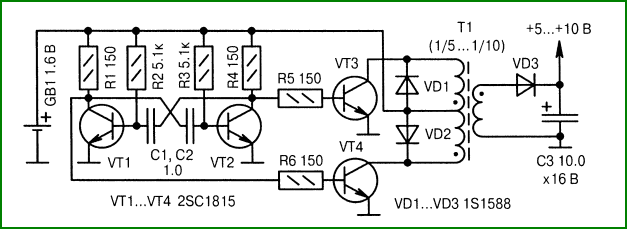
Unstabilized transistor converter:
This converter operates at a frequency of 50 kHz, galvanic isolation is provided by the T1 transformer, which is wound on a K10x6x4.5 ring made of 2000NM ferrite and contains: primary winding - 2x10 turns, secondary winding - 2x70 turns of PEV-0.2 wire. Transistors can be replaced with KT501B. The current from the battery, in the absence of load, is practically not consumed.
Second scheme. 
Transformer T1 is wound on a ferrite ring with a diameter of 7 mm, and contains two windings of 25 turns of wire PEV = 0.3.
Third scheme.
: 
Push-pull unstabilized converter based on a multivibrator (VT1 and VT2) and a power amplifier (VT3 and VT4). The output voltage is selected by the number of turns secondary winding pulse transformer T1.
Fourth scheme.
Converter on a specialized chip:
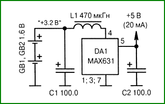
Stabilizing type converter on a specialized microcircuit from MAXIM. The generation frequency is 40 ... 50 kHz, the storage element is the L1 choke.
Fifth scheme.
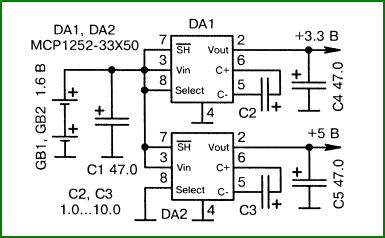
Unstabilized two-stage voltage multiplier:
You can use one of the two chips separately, for example the second, to multiply the voltage from two batteries.
Sixth scheme.
Switching step-up stabilizer on a MAXIM chip:
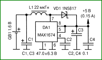
A typical circuit for switching on a pulse boost stabilizer on a MAXIM chip. Operation is maintained at an input voltage of 1.1 volts. Efficiency - 94%, load current - up to 200 mA.
Seventh scheme.
Two voltages from one power supply
: 
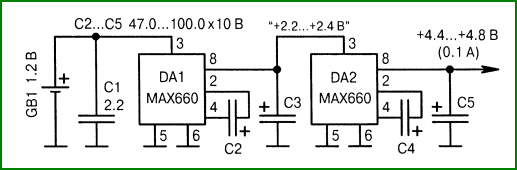
Allows you to receive two different stabilized voltages with an efficiency of 50 ... 60% and a load current of up to 150 mA in each channel. Capacitors C2 and C3 are energy storage devices.
Eighth scheme.
Switching step-up stabilizer on a microcircuit-2 from MAXIM:
A typical circuit for switching on a specialized microcircuit from MAXIM. Remains operational at an input voltage of 0.91 volts, has a small-sized SMD package and provides a load current of up to 150 mA with an efficiency of 90%.
Ninth scheme.
MINISTRY OF EDUCATION OF THE REPUBLIC OF MORDOVIA REGIONAL EDUCATIONAL DISTRICT
Competition research work students
"INTELLECTUAL FUTURE OF MORDOVIA"
Pulse voltage converter
Authors of the work: Mamonov Alexey, Golyatkin Alexey - students of the specialty " Technical operation and maintenance of electrical and electromechanical equipment"
GBOU RM SPO (SSUZ) "Saransk Electromechanical College"
Saransk 2013
Annotation. This paper proposes and discusses the circuit diagram and design of a pulsed DC-DC boost converter 12/220V. The developed small-sized 220V DC source powered by a 12V battery is designed for autonomous, bright and economical lighting of a house, garage, cottage when a centralized power supply is not available. The converter circuit is simple, reliable and has a set of inexpensive and affordable elements.
Introduction……………………………………………………………………………..…………...4
1. Theoretical part…………………………………………………..…………………………5
1.1 Main types of converters electrical energy………………….………5
1.2 Switching voltage converters …………...………………….…….……..6
2.Experimental part………………………………………..……………………...…….9
2.1. Development of a fundamental electrical circuit step-up DC-DC voltage converter 12/220V.……………………………………………..…...….9
2.2 Design, manufacturing technology and testing of the converter………..........10
2.3. Converter cost calculation..……………………………...…………..….11
Conclusion………………………………………………………………………..……….……12
List of used sources and literature…………………………..…...…………12
Introduction
Currently, a large selection of converters is offered on the electronic equipment market. They found wide application in various industries and at home. Voltage converters differ in their functionality, the shape of the output voltage, the output power and, accordingly, the price.
In this paper, we propose and discuss the schematic diagram and design of a 12/220V DC-DC boost converter. The main criteria in the development of the converter were small dimensions with high specific power, simplicity of technical solution, reliability and low price.
The purpose of the study is the development and manufacture of a small-sized 220V DC source powered by a 12V battery. Research objectives are:
To study and analyze the existing types of electrical energy converters.
Develop an optimal electrical circuit and design of a voltage converter for 12-220V.
Make a converter according to the developed scheme.
Test the converter, measure the input and output characteristics and draw conclusions about its performance.
Research methods: study of literature and Internet resources, observation, generalization, analysis, classification, modeling, forecasting, experiment, calculation, comparison, description.
The practical significance of the work. The developed voltage converter is a simple and inexpensive source of autonomous power supply for autonomous, bright and economical lighting of a house, garage, cottage when centralized power supply is unavailable.
Relevance of the topic. The device is relevant for owners of non-electric garden houses, garages, where the only source of electricity can be a car battery.
1. Theoretical part
1.1 The main types of electrical energy converters.
An electrical energy converter is an electrical device designed to convert electrical energy parameters (voltage, frequency, number of phases, waveform). Semiconductor devices are widely used to implement converters, since they provide high efficiency - an important parameter of electrical devices.
The main types of electrical energy conversion are:
· rectification of alternating current - converting alternating current into direct current (Fig. 1). This type of conversion is the most common, since some consumers of electrical energy can only operate on direct current (welding devices, electrolysis plants, etc.) or have higher technical and economic indicators on direct current than on alternating current (electric drive of the electric traction system , transmission lines of electrical energy of very high voltage);
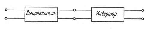
Rice. 2. The principle of operation of the inverter.
frequency conversion - usually alternating current an industrial frequency of 50 Hz is converted into alternating current of non-industrial frequency (power supply for adjustable AC drives, induction heating and metal melting installations, ultrasonic devices, etc.) (Fig. 3);
|
|
· conversion of the number of phases. Sometimes transformation is needed three-phase current into single-phase (for powering powerful electric arc furnaces) or vice versa, single-phase into three-phase (electrified transport). In industry, three-phase-single-phase frequency converters with a direct part are used, in which, along with the conversion of industrial frequency to a lower one, there is also a conversion three-phase voltage into single phase;
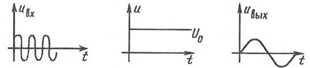
conversion of direct current of one voltage into D.C. other voltage (DC transformation) (Fig. 4). Such a conversion is necessary on a number of mobile objects, where the power source is a battery or other low voltage direct current source, and consumers require a higher voltage direct current (for example, to power radio equipment).
|
|

Rice. 4. The principle of operation of the DC voltage converter.
There are some other types of electrical energy conversion (for example, the formation of a certain curve AC voltage), in particular, the formation of powerful current pulses, which are used in special installations, adjustable AC voltage conversion. All types of transformations are carried out using power key elements.
The main types of semiconductor switches are diodes, power bipolar transistors, thyristors, gated thyristors, field controlled transistors.
1.2 Switching voltage converters
To convert the voltage of one level into a voltage of another level, pulse voltage converters are often used using inductive energy storage devices. Such converters are characterized by high efficiency, sometimes reaching 95%, and have the ability to obtain increased, reduced or inverted output voltage.
In accordance with this, three types of converter circuits are known: step-down, step-up and inverting. Five elements are common to all these types of converters: a power source, a key switching element, an inductive energy storage device (an inductor, a choke), a blocking diode, and a filter capacitor connected in parallel with the load resistance. The inclusion of these five elements in various combinations allows you to implement any of the three types of pulse converters.
The output voltage level of the converter is controlled by changing the width of the pulses that control the operation of the key switching element and, accordingly, the energy stored in the inductive storage device. The output voltage is stabilized by using feedback: when the output voltage changes, the pulse width changes automatically.
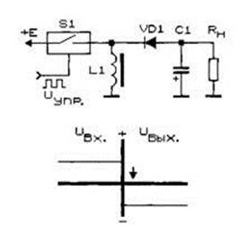
The step-down converter (Fig. 5) contains a series-connected circuit of a switching element S1, an inductive energy storage L1, a load resistance Rn and a filter capacitor C1 connected in parallel to it. The blocking diode VD1 is connected between the connection point of the key S1 with the energy storage L1 and a common wire.

Rice. 5. The principle of operation of the step-down voltage converter.
When the key is open, the diode is closed, the energy from the power source is stored in the inductive energy storage. After the switch S1 is closed (opened), the energy stored by the inductive storage L1 is transferred through the diode VD1 to the load resistance Rн. Capacitor C1 smooths out the voltage ripple.
The step-up pulse voltage converter (Fig. 6) is made on the same basic elements, but has a different combination of them: a series circuit of an inductive energy storage device L1, a diode VD1 and a load resistance with a filter capacitor C1 connected in parallel is connected to the power source. The switching element S1 is connected between the connection point of the energy storage device L1 with the diode VD1 and the common bus.

Rice. 6. The principle of operation of the step-up voltage converter.
When the switch is open, the current from the power source flows through the inductor, in which energy is stored. Diode VD1 is closed, the load circuit is disconnected from the power source, key and energy storage. The voltage on the load resistance is maintained due to the energy stored on the filter capacitor. When the key is opened, the self-induction EMF is added to the supply voltage, the stored energy is transferred to the load through the open diode VD1. The output voltage obtained in this way exceeds the supply voltage.
The pulse-type inverting converter contains the same combination of basic elements, but in a different connection (Fig. 7): a series circuit of a switching element S1, a diode VD1 and a load resistance Rn with a filter capacitor C1 is connected to the power source. The inductive energy storage L1 is connected between the connection point of the switching element S1 with the diode VD1 and the common bus.
Rice. 7. Pulse voltage conversion with inversion.
The converter works as follows: when the key is closed, energy is stored in an inductive storage. Diode VD1 is closed and does not pass current from the power source to the load. When the switch is turned off, the self-induction EMF of the energy storage device turns out to be applied to the rectifier containing the VD1 diode, the load resistance Rn and the filter capacitor C1. Since the rectifier diode passes only negative voltage pulses into the load, a negative voltage is formed at the output of the device.
There are other types of pulse voltage converters. Flyback converter - a kind of static pulse voltage converters with galvanic isolation of primary and secondary circuits. The main element of the flyback converter is a multi-winding storage choke, which is often called a transformer. There are two main stages of operation of the circuit: the stage of accumulating energy by the throttle from the primary source of electricity and the stage of outputting the energy of the throttle to secondary circuit(secondary circuits).
A push-pull converter is a voltage converter that uses a transformer to change the voltage of a power source. The advantage of push-pull converters is their simplicity. The push-pull converter is similar to the flyback converter, but is based on a different principle of operation (energy is not stored in the transformer core).
2.Experimental part
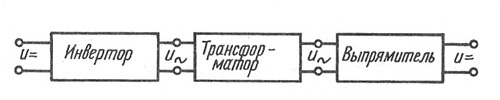
2.1. Development of a circuit diagram of a step-upDC- DCvoltage converter 12/220V
The principle of operation of the proposed converter is as follows: a direct current from a 12V battery is converted by an inverter into an alternating current of the same voltage, which is increased by a transformer to 220V and then rectified by a rectifier. A general view of the structure of the implemented converter is shown in fig. eight.
Rice. 8. Structural diagram of the voltage converter 12/220V.
circuit diagram converter is shown in fig. 9. The converter is built on a push-pull scheme. The basis of the converter is the well-known PWM controller chip TL494. This microcircuit has a built-in master oscillator, the frequency of which is set by an external R3C1 circuit. The operating frequency is set as follows: reduce the resistance R3 - increase the frequency. We increase the capacitance C1 - we decrease the frequency and vice versa. In this circuit, the frequency is about 100 kHz. Such high frequency conversion is due to the need to minimize the size of the converter transformer.
The circuit uses powerful IRFZ46N field-effect transistors, which are characterized by a shorter response time and more simple diagrams management. You can use IRFZ44N or IRFZ48N instead.
The step-up transformer in this converter is used from a computer power supply with a changed number of turns. The ratio of turns in the transformer is 1:1:20, where 1:1 is the two halves of the primary winding (10 + 10 turns), and 20 is, respectively, the secondary winding (200 turns). For the primary winding, a wire with a diameter of 0.5 mm is used, for the secondary winding - 0.3 mm.
The output voltage of the converter is taken from the secondary winding of the transformer and rectified by a bridge circuit made of high-speed KD213 diodes.

Rice. 9. Schematic diagram of the voltage converter 12/220V.
Protection of the circuit from overload and from incorrect power connection (polarity "+" and "-") can be implemented through a fuse and a diode at the input.
2.2. Design, manufacturing technology and testing of the converter
The appearance of the finished voltage converter is shown in fig. 10, where 1 - converter housing, 2 - input contacts, 3 - output contacts, 4 - fan.
http://pandia.ru/text/78/373/images/image015_24.jpg" width="276" height="265 src=">Acetone" href="/text/category/atceton/" rel="bookmark ">acetone.
To prevent overheating of transistors during long-term operation, a radiator and a fan are installed.
The finished converter has been tested for power energy saving lamps daylight basement type and incandescent lamps up to 40 W (Fig. 12).
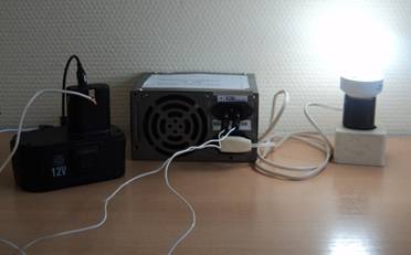
Rice. 12. Converter test.
As a result of the tests, the following data were obtained:
Input voltage is 12V, output voltage is 220+/-5V, maximum output power is 40W.
The converter was tested in both short-term and long-term operation modes (4 hours) with energy-saving and incandescent lamps different power up to 40W. In all cases, a normal bright glow without flickering was noted.
A comparative experiment on two lamps of the same rating, connected to a converter and to a socket with a voltage of 220V - 50Hz, showed visually the same result.
2.3. Converter cost calculation
The cost of the converter in terms of the cost of materials is 356 rubles. The calculation is shown in table No. 1. Average retail prices in specialized electronics stores are taken for calculation.
Table number 1. Calculation of the cost of the converter.
Materials and spare parts | Quantity, pcs. | Price per unit, rub. | Cost, rub. |
1. TL494 chip | |||
2. IRFZ46N transistors | |||
3. Resistor 2.6 kOhm | |||
4. Resistor 1 kOhm | |||
5. Resistor 10 kOhm | |||
6. Capacitor 500uF | |||
7. Capacitor 200uF | |||
8. Capacitor 1nF | |||
9. Transformer | |||
Conclusion
The developed small-sized 220V DC source powered by a 12V battery is designed for autonomous, bright and economical lighting of a house, garage, cottage when a centralized power supply is not available. The converter circuit is simple, reliable and has a set of inexpensive and affordable elements.
List of used sources and literature
1. GOST Electrical products. Terms and definitions of basic concepts.
2., Power electronics for amateurs and professionals - M .: SOLO-R, 2001. - 327p.
3. http://www. electromonter. info/theory/convert. html