Recently it was decided to build a 10W amplifier. There are many different specialized m / s on sale, but one friend recommended an amplifier based on the TDA2003 chip. This chip is of good quality and sound. It costs a penny these days. Even a beginner can assemble this amplifier, since in addition to the microcircuit itself, circuit diagram has only 9 parts. These parts can be purchased at any radio store, or obtained from old equipment. Scheme of a 10-watt ULF on TDA2003:
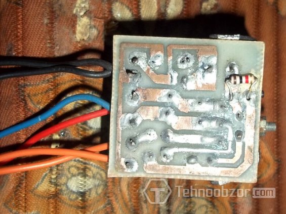
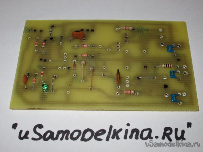
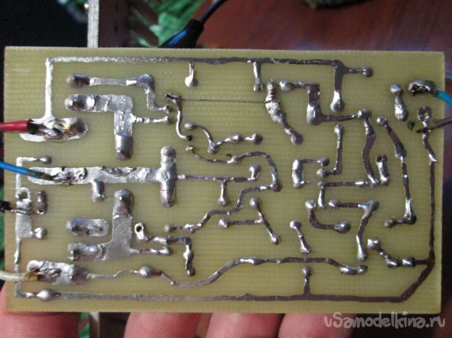
Perhaps many will have a problem with a 1 ohm resistor. It can be done by hand: taking a pencil and winding 10 turns of any wire thickness on it. By the way, the microcircuit can already work from 4.5v. I advise you not to apply more than 14v, because. thus, as a test, 2 microcircuits were burned. Rated power - 12v. In my case, three batteries were used from mobile phone. Having soldered them in series, I got 11.4v (3.8x3) at the output. After finding the right power source, I began to assemble the amplifier circuit. First, I redrawn the printed circuit board for convenience. I made a drawing on the glass sheet and etched everything unnecessary.
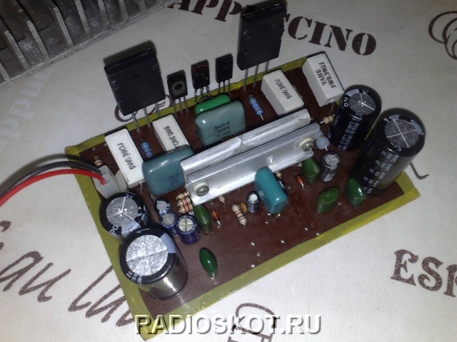
I soldered it in 15 minutes - the details are at least. I connected it to a low-power power source for testing - everything worked from the first turn on. At 11.1v, the amplifier produced about 10 watts of power. This is exactly what I need.

It is advisable to install the microcircuit on a small radiator, as it can overheat and fail. With a lack of radiator area (overheating), the microcircuit starts to play badly and clumsily. There is a printed circuit board in LAY format.

So, the hardest work remained - the manufacture of the case. This time I didn’t have to think for a long time: I took the box, pasted over it, installed the ULF circuit inside, made an output to the speakers and an input to the sound supply. I also added an LED that indicates power and its voltage. Everything else was placed in the body. Plays nice and loud. Happy repeating the design! Maxim Schaikow
12V battery in increased bipolar - you can proceed to the power amplifier itself. There are several channel amplifiers in the design.
TDA2005
- 20-25 watts are bridged. They are assembled on two separate boards for easy installation. Each of the amplifiers is activated when plus 12 volts is applied to the remote control output, this closes the relay and the amplifier is powered. Input capacitors can be selected to taste. Microcircuits are screwed onto a common heat sink through insulating gaskets.


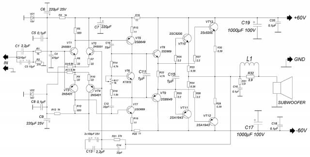

Zener diodes for 15 volts with a power of 1-1.5 watts, make sure they are installed correctly, when connected back they will work like a diode, there is a danger of burning the differential stage. Differential cascade - made on low-power complementary pairs, which can be replaced with others that are as similar as possible in terms of parameters. It is in this stage that the sound is formed, which is subsequently amplified and fed to the terminal (output stage). If you plan to make an amplifier for 100-150 watts, then you can exclude the second pair of the output stage, since the power of the amplifier directly depends on the supply voltage. With one pair of outputs, it is not advised to increase the supply voltage above +/-45 volts. If you are planning to assemble a subwoofer amplifier, then this circuit is what you need! variable resistor adjust the quiescent current of the amplifier, the further service life of the circuit depends on it.

Before soldering the tuning resistor R15, it must be “unscrewed” so that its impedance is soldered into the gap of the track. You need to take a multi-turn resistor, they can very accurately adjust the quiescent current, it is also very convenient for further tuning. But of course, if it is not already there, then you can get by with an ordinary trimmer, but it is advisable to remove it from the common board with wires, since after installing all the components, tuning will be almost impossible.
The quiescent current is adjusted after "heating the circuit", in other words, turn it on for 15-20 minutes, let it play, but don't get carried away! The quiescent current is an important factor, without correct setting the amplifier will not last long, the correct operation of the output stage and the level of constant at the output of the amplifier depend on it. The quiescent current can be found by measuring the voltage drop across a pair of emitter resistors (set the multimeter to the limit of 200mV, the probes to the VT10 and VT11 emitters). Calculation according to the formula: Ipok \u003d Uv / (R26 + R26). Next, smoothly rotate the trimmer and look at the readings of the multimeter. You need to set 70-100mA - this is equivalent to a multimeter reading (30-44) mV. Checking the level constant voltage at the exit. And now everything is ready - you can enjoy the sound of an amplifier assembled by yourself!

A small addition. Having assembled the UMZCH, you need to think about heat sinks. The main heat sink was taken from a domestic amplifier RADIO U-101 STEREO- it almost does not heat up during operation. Low-power diff-cascade transistors heat up, but overheating is not terrible, so they do not need cooling. The output transistors are screwed to the main heat sink through insulating gaskets, it is also desirable to use thermal paste, which I did not.

All other transistors can be installed on small separate heat sinks, or you can use a common one (for each stage), but in this case you need to screw the transistors through spacers. IMPORTANT ! All transistors must be screwed to the radiators through insulating gaskets, there should not be any short circuits on the bus, therefore, before turning on, carefully check with a multimeter whether the transistor leads are closed to the heat sink. We can consider the assembly of the device completed, but for today I say goodbye to you - AKA KASYAN.
Discuss the article AMPLIFIER WITH YOUR HANDS - BLOCK UMZCH
At one fine moment, I needed a final amplifier for the house, which would be part of the complex: PRIBOY E104S -> Radiotehnika UP-001 -> Final amplifier -> VEGA 50AS-106. The requirements were as follows: decent sound quality, the use of an existing construct. At the same time, I did not limit myself to ready-made circuitry research on the network or in amateur radio literature, but tried to create my own amplifier based on existing experience and material. This article is dedicated to this amplifier.
Since the electrical stuffing is still half the trouble, and for a radio amateur, the search for a housing is a headache that undermines the national health of our country, the problem of the housing should be addressed first of all. There are many options for solving the problem, I decided to take as a basis the body of the Soviet Elektron 104-stereo amplifier, released in 1977, and I strongly recommend that everyone look for this faulty amplifier for the future case and for the profitable borrowing of a step-down transformer (which will also be the main power element of the amplifier ). These amplifiers were almost universally used in theater circles, schools, kindergartens in assembly halls. I'm talking about the fact that it's time to start making "friends" in schools. The case of this amplifier is a vivid example of the wasteful use of aluminum, which allows you to use the possibilities of the case design for powerful amplifiers. At the same time, the disadvantage of this case is the proximity of one of the channels to the power transformer (blue arrow), which can give rise to such a phenomenon as the presence of a background amplifier in one of the channels, with a frequency that is a multiple of the mains frequency. Therefore, it was decided to move the location of the diode bridge (green arrow).
The power supply circuit has no features and is actually the power supply circuit of the original amplifier, but with a modified design. The final stage of placing the entire electrical component is illustrated below.

Now we can move on to the electrical part. The amplifier is a classic Lin topology, with modifications and additions. Amplifier parameters:
Characteristic - Value:
- Supply voltage range: ±24...35V
- Bandwidth, not narrower: 20-20000Hz
- Effective output power, at a load of 4 ohms and a supply of ± 35V: 80W
- Harmonic distortion factor, at maximum output power and input signal - sine 1kHz: 0.004%
- Harmonic distortion factor, at maximum output power and input signal - sine 20kHz: 0.02%
- Signal-to-noise ratio, at a frequency of 1kHz, not less than - 95dB
Sound amplifier circuit

The input stage of the power amplifier is assembled according to a differential circuit on transistors T3 and T4, loaded on a stable current generator, made according to the traditional classical pattern on transistor T5. Resistors R3, R4, R6, R7 are included in the emitters of the transistors of the differential stage, playing the role of local OOS, thus reducing the nonlinearity of the internal resistance of the emitter junction. The collector area of the input stage includes a current mirror on the elements T1 and T2, with additional resistors in the emitters to reduce the influence of the Earley effect, to achieve more accurate balancing of the input stage.
Further, the second stage of the amplifier is made on the transistor T6 according to the voltage amplifier circuit and has a bipolar correction. The bias circuit is made according to the “transistor zener diode” scheme using the T8 element. Installed on a radiator together with the output stage, it also performs the function of a thermal stabilizer. The inclusion of the quiescent current adjustment resistor R22 is designed in such a way as to ensure the safety of the circuit from accidental breakage of the removable contact engine, and in this regard, to prevent a sharp increase in the quiescent current of the output stage. Current is also supplied to the bias circuit from a stable current generator on transistor T7, which has a common reference voltage source with a generator for the differential stage (diodes D1, D2). The output stage is made according to a symmetrical scheme for switching on emitter followers. The output signal passes through the output filter R37L2 and the Zobel circuit (R36C8), which prevents the amplifier from self-exciting on high frequencies.
Some oscillograms

1) Sine 1kHz, 80W

2) Sine 20kHz, 80W

3) Square wave 1kHz

4) Square wave 1kHz
The design and details of a home audio amplifier
The L2 coil is wound on any pencil (pull the pencil out of the coil), with a wire with a cross section of 1 mm and contains 10-12 turns. The T8 transistor is mounted on the radiator, along with the output transistors. All transistors must be insulated from each other through mica spacers. To reduce the effect of temperature changes on the value of the DC voltage at the output of the amplifier, it is recommended to press transistors T1, T2 and T3, T4 in pairs with each other with PVC ties or heat shrink. Elements T9-T10 are located on separate aluminum plates (radiators), with a dispersion area of 30-40 cm2. The drawing of the printed circuit board is made under the existing construct, in my case the drawing was drawn on paper with a pencil. The universal circuit board, top view, looks like this (not tested or verified, errors are possible). its file can be found here.

ULF setting

The first switching on must be done through current-limiting resistors in the power supply, as well as with a load equivalent, after warming up and making sure that all circuit nodes are working normally, i.e. do not cause stressful situations for you and those around you. After that, a full-fledged power is supplied to the amplifier without removing the equivalent resistance. The trimmer resistor R15 achieves zero at the output of the amplifier, and the trimmer resistor R22 sets the quiescent current, in the range of 40-50 milliamps. Result: a really lively and good sound, excellent bottom (and this is on 50AC-106!), 4 copies were assembled, all started the first time.
Hi all! In this article I will describe in detail how to make a cool amplifier for home or car. The amplifier is easy to assemble and set up, and has good quality sound. Below is a schematic diagram of the amplifier itself.

The circuit is made on transistors and has no scarce parts. The power supply of the amplifier is bipolar +/- 35 volts, with a load resistance of 4 ohms. When connecting an 8 ohm load, the power can be increased to +/- 42 volts.
Resistors R7, R8, R10, R11, R14 - 0.5 W; R12, R13 - 5W; the rest 0.25 W.
R15 trimmer 2-3 kOhm.
Transistors: Vt1, Vt2, Vt3, Vt5 - 2sc945 (usually c945 is written on the case).
Vt4, Vt7 - BD140 (Vt4 can be replaced by our Kt814).
Vt6 - BD139.
Vt8 - 2SA1943.
Vt9 - 2SC5200.
ATTENTION! The c945 transistors have different pinouts: ECB and EBK. Therefore, before soldering, you need to check with a multimeter.
The LED is ordinary, green, exactly GREEN! He's not here for beauty! And it should NOT be super bright. Well, the rest of the details can be seen in the diagram.
And so, let's go!
To make an amplifier, we need tools:
- soldering iron
-tin
- rosin (preferably liquid), but you can get by with the usual
- metal scissors
-cutters
-awl
- medical syringe, any
- drill 0.8-1 mm
- drill 1.5 mm
- drill (preferably some kind of mini drill)
-sandpaper
-and a multimeter.
Materials:
- one-sided textolite board measuring 10x6 cm
- sheet of notebook paper
-a pen
- varnish for wood (preferably dark color)
- small container
-baking soda
-lemon acid
-salt.
I will not list the list of radio components, they can be seen on the diagram.
Step 1 We are preparing a fee
And so, we need to make a board. Since I don’t have a laser printer (I don’t have any at all), we will make the board “the old fashioned way”!
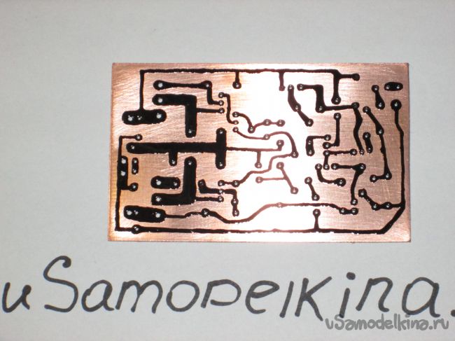
First you need to drill holes on the board for future parts. Who has a printer, just print this picture:

if not, then we need to transfer the markings for drilling to paper. How to do this you will understand in the photo below:

when you translate, do not forget about the fee! (10 by 6 cm)


something like that!
We cut off the size of the board we need with metal scissors.

Now we apply the sheet to the cut out board and fix it with adhesive tape so that it does not move out. Next, we take an awl and outline (by points) where we will drill.

Of course, you can do without an awl and drill right away, but the drill can move out!

Now you can start drilling. We drill holes 0.8 - 1 mm. As I said above: it is better to use a mini drill, since the drill is very thin and breaks easily. For example, I use a screwdriver motor.


Holes for transistors Vt8, Vt9 and for wires are drilled with a 1.5 mm drill. Now we need to clean our board with sandpaper.

Now we can start drawing our paths. We take a syringe, grind off a needle so that it is not sharp, we collect varnish and go!

It is better to trim the jambs when the varnish has already hardened.
Step 2 We charge a fee
For board etching, I use the simplest and cheapest method:
100 ml peroxide, 4 teaspoons citric acid and 2 teaspoons of salt.

We stir and immerse our board.


Next, we clean the varnish and it turns out like this!

It is advisable to immediately cover all the tracks with tin for the convenience of soldering parts.

Step 3 Soldering and tuning
It will be convenient to solder according to this picture (view from the side of the parts)

For convenience, from the beginning we solder all the small parts, resistors, etc.
And then everything else.

After soldering, the board must be washed from rosin. You can wash it with alcohol or acetone. On kraynyak it is possible even gasoline.
Now you can try to turn it on! With proper assembly, the amplifier works immediately. When you first turn on the resistor R15 must be turned in the direction of maximum resistance (we measure it with a device). Do not connect the column! The output transistors are MANDATORY on the radiator, through insulating gaskets.
And so: turn on the amplifier, the LED should be on, we measure the output voltage with a multimeter. There is no standing, so everything is fine.
Next, you need to set the quiescent current (75-90mA): to do this, close the input to ground, do not connect the load! On the multimeter, set the mode to 200mV and connect the probes to the collectors of the output transistors. (marked with red dots in the photo)

Next, by slowly rotating the resistor R15, you need to set 40-45 mV.

Exposed, now you can connect the speaker and drive the amplifier at a low volume for 10-15 minutes. Then again it will be necessary to correct the quiescent current.
Well, that's all, you can enjoy!
Here is a video of the amplifier in action:
The simplest transistor amplifier can be a good tool for studying the properties of devices. The schemes and designs are quite simple, you can independently manufacture the device and check its operation, measure all parameters. Thanks to modern field-effect transistors, it is possible to make a miniature microphone amplifier literally from three elements. And connect it to a personal computer to improve the sound recording parameters. And the interlocutors during conversations will hear your speech much better and more clearly.
Frequency characteristics
Low frequency (audio) frequency amplifiers are available in almost all household appliances- music centers, televisions, radios, radios, and even in personal computers. But there are also high-frequency amplifiers on transistors, lamps and microcircuits. Their difference is that ULF allows you to amplify the signal of only the audio frequency, which is perceived by the human ear. Transistor audio amplifiers allow you to reproduce signals with frequencies in the range from 20 Hz to 20,000 Hz.
Therefore, even the simplest device is able to amplify the signal in this range. And it does it as evenly as possible. The gain depends directly on the frequency of the input signal. The graph of the dependence of these quantities is almost a straight line. If, on the other hand, a signal with a frequency outside the range is applied to the input of the amplifier, the quality of work and the efficiency of the device will quickly decrease. ULF cascades are assembled, as a rule, on transistors operating in the low and medium frequency ranges.
Classes of operation of audio amplifiers
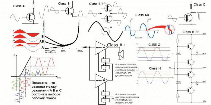
All amplifying devices are divided into several classes, depending on what degree of current flow through the cascade during the period of operation:
- Class "A" - the current flows non-stop during the entire period of operation of the amplifying stage.
- In the class of work "B" current flows for half the period.
- Class "AB" indicates that the current flows through the amplifying stage for a time equal to 50-100% of the period.
- In "C" mode electricity runs for less than half of the operating time.
- Mode "D" ULF has been used in amateur radio practice quite recently - a little over 50 years. In most cases, these devices are implemented on the basis of digital elements and have a very high efficiency - over 90%.
The presence of distortion in various classes of low-frequency amplifiers
The working area of a class "A" transistor amplifier is characterized by rather small non-linear distortions. If the incoming signal throws out higher voltage pulses, this causes the transistors to saturate. In the output signal, higher harmonics (up to 10 or 11) begin to appear near each harmonic. Because of this, a metallic sound, characteristic only for transistor amplifiers, appears.
With an unstable power supply, the output signal will be modeled in amplitude near the mains frequency. The sound will become harsher on the left side of the frequency response. But the better the power stabilization of the amplifier, the more complex the design of the entire device becomes. ULF operating in class "A" have a relatively low efficiency - less than 20%. The reason is that the transistor is constantly on and current flows through it constantly.
 To increase (albeit insignificant) efficiency, you can use push-pull circuits. One disadvantage is that the half-waves of the output signal become asymmetrical. If you transfer from class "A" to "AB", the non-linear distortion will increase by 3-4 times. But the coefficient useful action the entire circuit of the device will still increase. ULF classes "AB" and "B" characterizes the increase in distortion with a decrease in the signal level at the input. But even if you turn up the volume, it will not help to completely get rid of the shortcomings.
Work in intermediate classes
Each class has several varieties. For example, there is a class of amplifiers "A +". In it, the transistors at the input (low-voltage) operate in the "A" mode. But high-voltage, installed in the output stages, work either in "B" or in "AB". Such amplifiers are much more economical than those operating in class "A". A noticeably smaller number of non-linear distortions - no higher than 0.003%. Better results can be achieved using bipolar transistors. The principle of operation of amplifiers on these elements will be discussed below.
But still there are a large number of higher harmonics in the output signal, which makes the sound characteristic metallic. There are also amplifier circuits that work in the "AA" class. In them, non-linear distortion is even less - up to 0.0005%. But the main drawback of transistor amplifiers is still there - a characteristic metallic sound.
"Alternative" designs
 It cannot be said that they are alternative, just some specialists involved in the design and assembly of amplifiers for high-quality sound reproduction are increasingly preferring tube designs. Tube amplifiers have the following advantages:
- Very low level of non-linear distortion in the output signal.
- There are fewer higher harmonics than in transistor designs.
But there is one huge minus that outweighs all the advantages - you must definitely install a device for coordination. The fact is that the tube cascade has a very high resistance - several thousand ohms. But the speaker winding resistance is 8 or 4 ohms. To match them, you need to install a transformer.
Of course, this is not a very big drawback - there are also transistor devices that use transformers to match the output stage and the speaker system. Some experts argue that the most effective circuit is a hybrid - in which single-ended amplifiers are used that are not covered by negative feedback. Moreover, all these cascades operate in the ULF class "A" mode. In other words, a transistorized power amplifier is used as a repeater. 
Moreover, the efficiency of such devices is quite high - about 50%. But you should not focus only on efficiency and power indicators - they do not talk about high quality sound reproduction by an amplifier. Much more important are the linearity of the characteristics and their quality. Therefore, you need to pay attention first of all to them, and not to power.
Scheme of a single-ended ULF on a transistor
The simplest amplifier, built according to the common emitter circuit, operates in class "A". The circuit uses a semiconductor element with an n-p-n structure. A resistance R3 is installed in the collector circuit, which limits the flowing current. The collector circuit is connected to the positive power wire, and the emitter circuit is connected to the negative. In the case of using semiconductor transistors with the structure p-n-p scheme will be exactly the same, only you need to change the polarity.
With the help of a coupling capacitor C1, it is possible to separate the AC input signal from the DC source. In this case, the capacitor is not an obstacle to the flow alternating current along the base-emitter path. The internal resistance of the emitter-base junction, together with resistors R1 and R2, is the simplest supply voltage divider. Typically, resistor R2 has a resistance of 1-1.5 kOhm - the most typical values \u200b\u200bfor such circuits. In this case, the supply voltage is divided exactly in half. And if you power the circuit with a voltage of 20 Volts, you can see that the value of the current gain h21 will be 150. It should be noted that HF amplifiers on transistors are made according to similar circuits, only they work a little differently.
 In this case, the emitter voltage is 9 V and the drop in the “E-B” circuit section is 0.7 V (which is typical for transistors based on silicon crystals). If we consider an amplifier based on germanium transistors, then in this case the voltage drop in the “EB” section will be 0.3 V. The current in the collector circuit will be equal to that which flows in the emitter. You can calculate by dividing the emitter voltage by the resistance R2 - 9V / 1 kOhm = 9 mA. To calculate the value of the base current, it is necessary to divide 9 mA by the gain h21 - 9mA / 150 \u003d 60 μA. ULF designs usually use bipolar transistors. The principle of its work is different from the field.
On the resistor R1, you can now calculate the drop value - this is the difference between the base and supply voltages. In this case, the base voltage can be found by the formula - the sum of the characteristics of the emitter and the "E-B" transition. When powered by a 20 Volt source: 20 - 9.7 \u003d 10.3. From here, you can calculate the resistance value R1 = 10.3V / 60 μA = 172 kOhm. The circuit contains capacitance C2, which is necessary for the implementation of the circuit through which the alternating component of the emitter current can pass.
If you do not install capacitor C2, the variable component will be very limited. Because of this, such a transistor audio amplifier will have a very low current gain h21. It is necessary to pay attention to the fact that in the above calculations the base and collector currents were assumed to be equal. Moreover, the base current was taken to be the one that flows into the circuit from the emitter. It occurs only when a bias voltage is applied to the output of the base of the transistor.
 But it must be borne in mind that absolutely always, regardless of the presence of bias, the collector leakage current necessarily flows through the base circuit. In circuits with a common emitter, the leakage current is increased by at least 150 times. But usually this value is taken into account only when calculating amplifiers based on germanium transistors. In the case of using silicon, in which the current of the "K-B" circuit is very small, this value is simply neglected.
MIS transistor amplifiers
The field-effect transistor amplifier shown in the diagram has many analogues. Including using bipolar transistors. Therefore, we can consider as a similar example the design of a sound amplifier assembled according to a common emitter circuit. The photo shows a circuit made according to a circuit with a common source. R-C connections are assembled on the input and output circuits so that the device operates in the class “A” amplifier mode.
Alternating current from the signal source is separated from the DC supply voltage by capacitor C1. Be sure the field-effect transistor amplifier must have a gate potential that will be lower than that of the source. In the presented diagram, the gate is connected to a common wire through a resistor R1. Its resistance is very large - resistors of 100-1000 kOhm are usually used in designs. Such a large resistance is chosen so that the signal at the input is not shunted.
 This resistance almost does not pass electric current, as a result of which the potential of the gate (in the absence of a signal at the input) is the same as that of the ground. At the source, the potential is higher than that of the ground, only due to the voltage drop across the resistance R2. From this it is clear that the potential of the gate is lower than that of the source. Namely, this is required for the normal functioning of the transistor. It should be noted that C2 and R3 in this amplifier circuit have the same purpose as in the design discussed above. And the input signal is shifted relative to the output signal by 180 degrees.
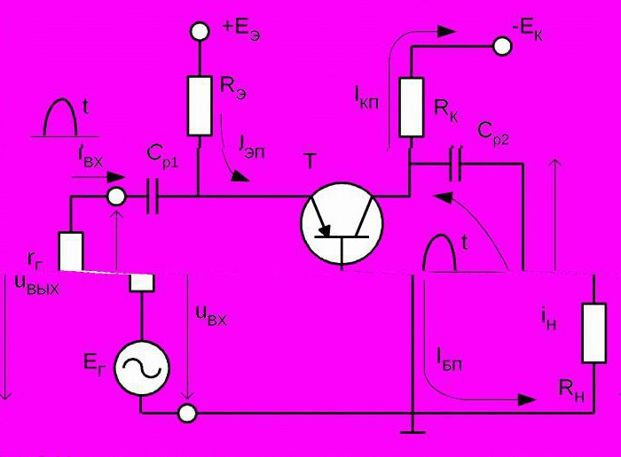
ULF with output transformer
 You can make such an amplifier with your own hands for home use. It is carried out according to the scheme that works in class "A". The design is the same as discussed above - with a common emitter. One feature - it is necessary to use a transformer for matching. This is a disadvantage of such a transistor audio amplifier.
 The collector circuit of the transistor is loaded with a primary winding, which develops an output signal transmitted through the secondary to the speakers. A voltage divider is assembled on resistors R1 and R3, which allows you to select the operating point of the transistor. With the help of this circuit, a bias voltage is supplied to the base. All other components have the same purpose as the circuits discussed above.
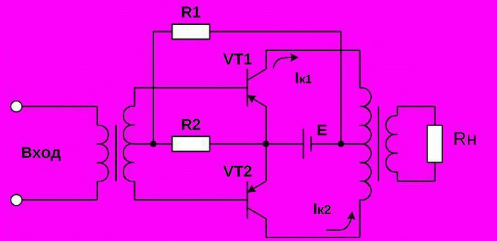
push-pull audio amplifier
This is not to say that this is a simple transistor amplifier, since its operation is a little more complicated than that of those discussed earlier. In push-pull ULF, the input signal is split into two half-waves, different in phase. And each of these half-waves is amplified by its own cascade, made on a transistor. After each half-wave has been amplified, both signals are combined and sent to the speakers. Such complex conversions can cause signal distortion, since the dynamic and frequency properties of two, even of the same type, transistors will be different.
 As a result, the sound quality at the output of the amplifier is significantly reduced. When a push-pull amplifier in class "A" is working, it is not possible to reproduce a complex signal with high quality. The reason is that the increased current flows constantly through the arms of the amplifier, the half-waves are asymmetrical, and phase distortions occur. The sound becomes less intelligible, and when heated, signal distortion increases even more, especially at low and ultra-low frequencies.
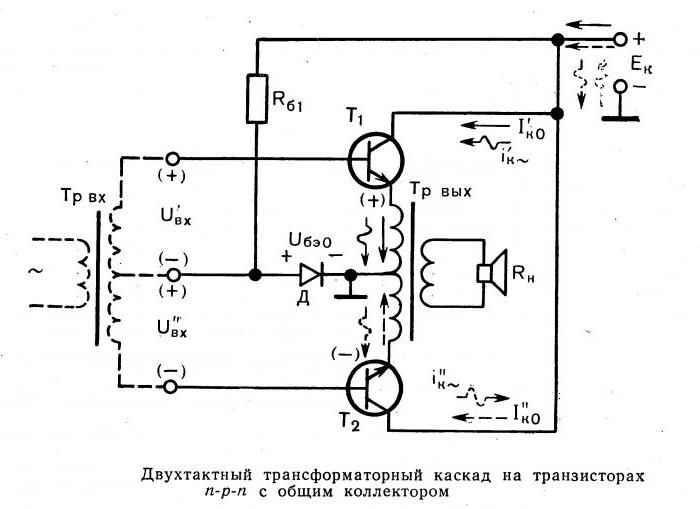
Transformerless ULF
The low-frequency amplifier on a transistor, made using a transformer, despite the fact that the design may have small dimensions, is still imperfect. Transformers are still heavy and bulky, so it's best to get rid of them. A much more efficient circuit is made on complementary semiconductor elements with different types of conductivity. Most of modern ULF is performed exactly according to such schemes and work in class "B".
Two powerful transistors, used in the design, work according to the scheme of the emitter follower (common collector). In this case, the input voltage is transmitted to the output without loss and amplification. If there is no signal at the input, then the transistors are on the verge of turning on, but still turned off. When a harmonic signal is applied to the input, the first transistor opens with a positive half-wave, and the second one is in the cutoff mode at this time.
 Therefore, only positive half-waves can pass through the load. But negative ones open the second transistor and completely block the first one. In this case, only negative half-waves are in the load. As a result, the signal amplified in power is at the output of the device. Such a transistor amplifier circuit is quite effective and is able to provide stable operation, high-quality sound reproduction.
ULF circuit on one transistor
Having studied all the above features, you can assemble an amplifier with your own hands on a simple element base. The transistor can be used domestically KT315 or any of its foreign analogues - for example BC107. As a load, you need to use headphones, the resistance of which is 2000-3000 ohms. A bias voltage must be applied to the base of the transistor through a 1 MΩ resistor and a 10 µF decoupling capacitor. The circuit can be powered from a source with a voltage of 4.5-9 Volts, current - 0.3-0.5 A.
 If the resistance R1 is not connected, then there will be no current in the base and collector. But when connected, the voltage reaches a level of 0.7 V and allows a current of about 4 μA to flow. In this case, the current gain will be about 250. From here, you can make a simple calculation of the transistor amplifier and find out the collector current - it turns out to be 1 mA. Having assembled this transistor amplifier circuit, you can test it. Connect the load - headphones to the output.
Touch the input of the amplifier with your finger - a characteristic noise should appear. If it is not there, then most likely the design is assembled incorrectly. Recheck all connections and element ratings. To make the demonstration clearer, connect a sound source to the ULF input - the output from the player or phone. Listen to music and appreciate the sound quality.