, , , , , , , , , , , , , , , , , , , , , , , , , , , , , , , , , , , , , , , , , , , , , , , , , , , , , , , , , , , , , , , ,
OZ960
To disable protection at the SoftStart input (pin 4 of the OZ960 chip), you must force a voltage of 1.5V - 3.5V to this input (pin 4), which will control the duration of the PWM pulses and regulate the output current in the lamps.
Information courtesy of a Rottor member on the monitor.net.ru repair forum
Another original solution to disable OZ960 protection via pin-10 from an AMIT participant.
Quote:
0Z960
very easy way to unprotect. put the LED with 10 feet on the ground.(6 foot chip)
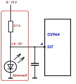
OZ964
From forum member monitor.net.ru KRAB
Quote:
Removal of protection for OZ964:
At pin 4 (SST - Soft-Start Time), at the moment of switching on, you need to hold 1.8 - 2V.
From forum member monitor.net.ru X1-42
Quote:
OZ964 protection is removed in the same way as OZ960, LED for pin 10.
From forum member monitor.net.ru CAIIIA
Quote:
In the LCD LG 32LK330-ZB Inverter VIT71884.00 REV:2.LOGAH (OZ964 + LM339) it was not possible to win, sometimes it works, sometimes it doesn’t, but it was possible to turn off the protection only simultaneously for 4 and 10 legs. Separately, the protection was not blocked.
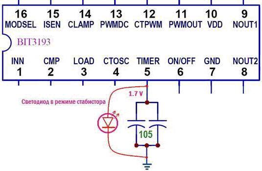
BIT3193
Information provided by KRAB member:
Quote:
Removing protection for BIT3193:
When the protection is triggered, the voltage at pin 5 is about 3.5 V.
When the voltage at pin 5 is from 0.4 to 2.4V and the “start” command is given, the PWM works autonomously, the lamps do not turn off.
Removing protection for BIT3193:
(victor_loza monitor.net.ru)
Option 1
Through a resistor 2 - 3 kΩ, connect pin 5 to pin 12 of the microcircuit, thus holding the "working" potential of about 1.2 V.
Option - 2
Connect the LED as a stabistor to pin 5 to ground in direct connection, "stabilizes" the voltage at pin 5, up to 06 - 08 volts
None of the options work...
The second option with LED works for me. (merkyrio).
TL1451
More information from KRAB:
Quote:
Remove protection TL1451:
- Protection blocking in the TL1451 chip (analogous to BA9741) is reduced to a simple action by closing pin 15 to ground.
But if this is done after the protection has been triggered (for example, with tweezers), then nothing happens because the trigger protection is already blocked from feedback sensors.
- To restore functionality, you need to reset the protection trigger by turning off and on the inverter again or by changing the level at pin 9 of the microcircuit.
When the monitor is running, the protection trigger reset is updated automatically.
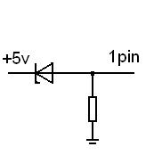
FAN7314
From monitor.net.ru forum member Valentin
Quote:
BN44-00182C with live transformers in the inverter, I decided to throw trances on the well-known ... 123rd block, paralleled the primary trances,
and on the 1st leg of the FAN7314 I put a zener diode at 4.3v with + 5v and a 620 ohm resistor on the case.
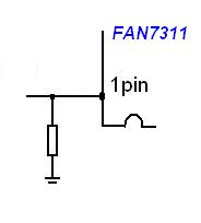
FAN7311 - FAN7314
From monitor.net.ru participant Parazetam0l
Quote:
Controllers FAN7311 - FAN7314
According to the Valentin method, (on this page) - a 560 Ohm resistor, from pin 1 to the case.
A zener diode is not needed, in this inclusion it still does not work.
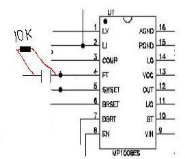
MP1008
Information provided by ancl:
Quote:
Deprotection from MP1008: 10 kOhm from 4 pins of MP1008 to the case.
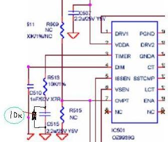
OZ9938Q
Information provided by member JUDI71:
Quote:
The protection is removed, 10k parallel to the conder, 3 pins OZ9938 each.
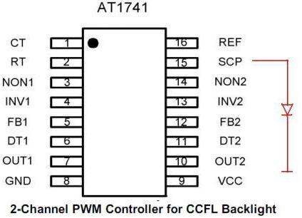
AT1741
Information provided by asanik:
Quote:
AT1741S - LED with 15 pins to ground. I'm guessing a resistor.
The LED is not lit.
BD9897
Information provided by fantom555:
Quote:
BD9897 has 17 pins. ... you "hang" an LED from it to ground in direct connection and the driver starts to "thresh" no matter what.
BD9897F
Information provided by status DNA contributor:
Quote:
BD9897F on the 22nd output of the SCP chip, hang the LED, cathode to ground.
BD9897FS
Information provided by comporator:
Quote:
Apparatus LCD Sharp LC-32A47l, 6-lamp inverter on BD9897FS. It was necessary to bypass the protection of BD9897FS, one of the secondary pipes shorted in a trance - the winding was removed. For a long time I tried to do something on the feedback, nothing happened. As a result, I put the LED on the 17 pin BD9897 in direct connection and on the case, which immediately turned off the protection. The device has earned, successfully passed the run and issued.
TA9687GN
Information provided by member gchel:
Quote:
TA9687GN ---- connect the 12th pin of TIMER through 47kΩ to the housing (parallel to C818). Checked.
Information provided by the participant serge fetyunin:
Quote:
TA9687GN instead of a resistor, an LED is placed and the brightness control remains.
BD9883
Information provided by an AMIT member:
Quote:
any LED, 13 leg-SS, BD9883 microcircuits, --- anode, case ---- 7, cathode
or just put 12 feet on the ground.
Information provided by Captain:
Quote:
OZ99361
Information provided by Nlfjk:
Quote:
Disabling protection in the OZ99361 chip.
... set the voltage at pin 1 of the microcircuit with the regulator within the limits of a stable start of 1.85 - 1.98V
Quote:
OZ9910GN
Information provided by member evg4682:
Quote:
Controller QZ9910 GN protection off: LED with 3 legs stabistor. Works with one lamp, only contrast is adjustable. Aser al1716 monitor.
More options from other forums:
BIT3102A
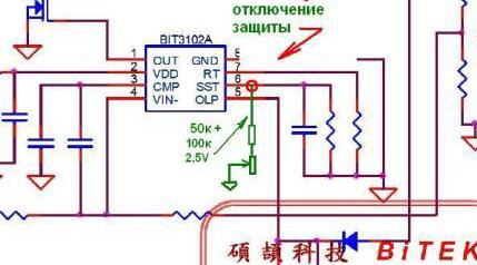
From participant monitor.net.ru maksatiha
Quote:
Disable protection per ms BIT3102A. The protection is disabled if the 6th leg is put on the ground through R = 40 kOhm. Verified personally. I had to do this when I installed BN44-00082C block instead of MT2-17 REV0.2 in Samsung N920
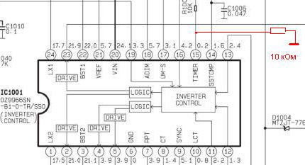
OZ9966SN
From monitor.espec.ws zuev-tv
Quote:
LCD TV inverter on OZ9966SN - a way to disable protection.
LX1691A
Quote:
MP1009
From monitor.net.ru member Benzopiren
Quote:
Disable protection MP1009 - Short pin 5 to ground.
OZT1060GN
Quote:
OZT1060GN - led diode pin1
QZ9938GN
From monitor.net.ru member bdvrt
Quote:
QZ9938GN - LED pin3 ...as for bit3193
MP10072E
From monitor.net.ru participant gosha_gor
Quote:
Removal of protection in IC type MP10072E: 3 pin - LED on the case.
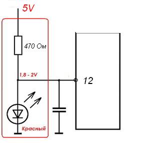
INL837GL
From participant monitor.net.ru Benzopiren
Quote:
INL837GL Stabilize the power at pin 12 - 1.7 - 2 V. Connect the stabistor (LED) from pin 12 to ground, and supply power from the 5 V source through a 470 - 510 Ohm resistor there.
OZ99361
From monitor.net.ru member kebastos
Quote:
I’ll add on the LG 26LC2RA ..... the LC260WX2 panel, the master-slave inverter, the master is assembled on OZ99361 ..... you can change to 9936, but that’s not the point .... the inverter is chopped after turning on after three seconds ...... turning off its protection was invented and is on the internet: see the photo below ..... (turning off the protection in this case is not dangerous because the inverter is cut due to run-down lamps) .... but! with such refinement it it works, everything is fine, but in the modes of the "standard" type and on AV1, the inverter starts to squeal like a cut dog, while working ....... my alteration is a little different - we hang 1 paw of the micra in the air, and connect it through the cutter 100 kOhm to 5 volts .... in the figure it is clay going to the 6th foot of the micro .... well, between 1 foot of the micro and the ground - a 0.15 microfarad conder, and that's it - it works fine silently in all modes
MP1038
Quote from Sergei Ganz:
Removal of protection from the MP1038 - the 6th leg of the driver (FT) through 10 kOhm to the case. (By analogy with MP1008, only there FT is the 4th leg).
MP1038EY
From monitor.net.ru member rammer
Quote:
MP1038EY - LED on the 6th pin Fault Timing.
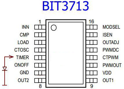
BIT3713
Quote:
BIT3713 - LED with 5 TIMER pins to ground. The LED is not lit.
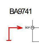
BA9741
From monitor.net.ru participant asanik
Quote:
BA9741 F 15 pin - connect SCP to ground. Thus, protection is blocked on both channels of the driver. (LCD CAMERON 1501SP)
SEM2105
From monitor.net.ru member ra4llb
Quote:
SEM2105 - to block, put the LED on 1 pin of the IC.
MAX8722
Quote:
max8722 - to block, put 4 pins on the ground.
SEM2006
Quote:
SEM2006 - Protection is removed by LED from 2 pins on the case.
MSC1692
From participant monitor.net.ru yuri 72
Quote:
MSC1692 - with 4 pins 220kΩ resistor on the case.
KH0803A
From participant monitor.net.ru yuri 72
Quote:
KH0803A - LED or R 390 - 820 kOm with 5 pins per case. (parallel to C125).
SP5005
From participant monitor.net.ru Altai
Quote:
SP5005 - (sop16 4ccfl) LED with 5 (timer) pins on the body. OZ9910 in my case turned off the LED protection from pin 10 (and not from the 9th)
SP5001Q
From participant Anatoly Boldorev
Quote:
TV SANSUI LT2202SS.
Chip SP 5001Q. LED with 19 feet on the common wire of the cathode.
MP1027EF
From participant monitor.net.ru Rishat-80
Quote:
Another way to disable the PWM protection of the MP1027EF controller. A rare controller, mainly installed on ADVANTECH industrial monoblocks. PWM controller with 20 pins, you need to connect the 16th pin to GND via a red LED.
BD9240
From monitor.net.ru participant jurez
Quote:
BD9240 You can remove the protection by putting the 15th leg (CP) through 10 kOhm on the case. The panel backlight adjustment stops working.
OB3316QP
Quote:
OB3316QP you can remove the protection like this: by putting an LED with a 5-pin IMs on ground.
BD9884VF
Quote:
bd9884VF
Removal of protection tested on Erisson 26LH01 --- 17 pin of the microcircuit is connected to a voltage divider - cut off the track after the divider, which goes to the op amp - error amplifier.
OB3328UQP
From monitor.net.ru member Radiogad
Quote:
OB3328UQP
To remove the protection, it is enough to install the LED with a 3pin IC to ground.
From participant monitor.net.ru key-s
Quote:
10k resistor, from pin 3 to ground. The native conder on this pin is soldered, in its place is a resistor. Favorite inverter TV3203-ZC02-02(A)
BI3101
From monitor.net.ru member olegno11
Quote:
Disabling protection in the BI3101 chip
Conclusion 16 of the microcircuit is closed to a common wire with a resistor of 220 - 470 Ohm
BD9882F
From monitor.net.ru member Kolya
Quote:
BD9882F
LED from the 14th output to ground.
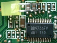
BD9766VF
From monitor.net.ru participant LGbakht-tel
Quote:
BD9766VF.
LED from the 20th pin to ground.
OB3309
From remont-aud.net member AleksandKn
Quote:
According to the OB3309 datasheet, 15pin STIME should be +2V. I put a 15pin LED on the case with a voltage of 1.7V. The backlight works and nothing gets hot. In the shim harness, all resistors are normal, the image parameters are adjustable.
FAN7316
Oleg Nemtsov [email protected]
Quote:
LED on pin 17.
BD9211F
From monitor.net.ru member HMAO
Quote:
The backlight turned off, I installed a 4.7kΩ resistor on the 14th output and the case.
BD9261FP
From monitor.net.ru member LEX1
Quote:
Protection blocking is carried out by setting St. diode between 27 (6) m / s terminal and case.
SAQ8818
From monitor.net.ru member idnavi
Quote:
To block the protection, it is enough to solder a 1MΩ resistor with +12 Volts (inverter power) to the 7th pin of SAO8818. SAQ8818 is placed TL494 with a 180 degree turn.
MP1006
From monitor.net.ru participant Vladislav_
Quote:
MP1006 remove the protection by setting a resistance of 10 K from the 6th output "FT" to the case.
SEM2107
From monitor.net.ru participant rostik-71
Quote:
SEM2107 TV KTC, inverter SSI_400_14A01 rev 0.1.
Solder the LED to the 21st output of the IC (SDT).
FAN7547
From monitor.net.ru participant emer6
Quote:
Monitor Viewsonic-VA712B. Bypassing the inverter protection on the FAN7547 - we close the 7th leg of the microcircuit to the case.
OB3302CP
Quote:
OB3302CP protection was removed by installing a 2-pin LED at 3 volts.
BD9777
Quote:
BD9777 14 pin (SS) - microcircuits through a 10 kΩ resistor to ground.
OZL68GN
Quote:
OZL68GN removed protection with a white LED on the SST 4pin output.
BIT3105
From participant monitor.net.ru CAIIIA
Quote:
BIT3105 Removal of protection on the SST pin (19) with a white three-volt LED to ground. The brightness is good, 2.3V is retained at the output with such an LED.
BD9222FV
From participant monitor.net.ru ANOD07
Quote:
BD9222FV - LED with 13 pins to ground. LED does not light up
DT8211
From monitor.net.ru member gchel
Quote:
DT8211 9 foot on the case through a kilo-ohm resistor, for example 47k.
OZ9972
From monitor.net.ru member rz6anh
Quote:
OZ9972. Variant with 24 pins. Pin 20 (prot) through 1 kOhm to the case. The output from the circuit did not turn off. (rz6anh)
OZ9972ASN 24-pin package, 19 pin through 10 kOhm to ground (there are also 28-pin cases where pin 23 performs this function) (KAP1 monitor.net.ru).
UBA2070
From monitor.net.ru member zharinov
Quote:
UBA2070 - 1st leg to ground.
BD9896
From monitor.net.ru member fantom555
Quote:
BD9896 you hang an LED in direct connection from the 3rd pin to ground and the inverter works no matter what.
BD9215AFV
From monitor.net.ru participant LGbakht-tel
Quote:
BD9215AFV put a 10 kΩ resistor from IC pin 15 to ground.
ILN816GN
From monitor.net.ru member slfl
Quote:
ILN816GN - Disable protection on BENQ E2420HD. I removed the protection by installing a 10kΩ resistor on the eighth pin, in parallel with the capacitor C3.
UBA2074
From monitor.net.ru member Iskander
Quote:
UBA2074 for unprotection - 20 kOhm per case from pin 6. (6pin - CT - fault timing capacitor).
OZ9919GN
From participant monitor.net.ru artur58
Quote:
OZ9919GN 8pin through 10k to ground.
SEM2005
From participant monitor.net.ru nem
Quote:
SEM2005 - Protection is removed by LED from 1 pin per case.
MP1007ES
From monitor.net.ru participant LGbakht-tel
Quote:
MP1007ES 4pin to ground.
BD9276EFV
From monitor.net.ru participant Vlad-1966
Quote:
I removed the protection with a 35-pin LED (softstart).
BIT3251, BIT3252, BIT3267
From participant monitor.net.ru RadioElektronik
Quote:
The protection was removed by shorting 5 pins to ground.
BIT3267 is similar (monitor.net.ru shamrin).
OZ9643N
From participant monitor.net.ru xen
Quote:
OZ9643n - 1st pin through 20 kOhm to ground.
DDA009
From monitor.net.ru member vovan_j
Quote:
DDA009. Apply 3v to pin 18 (VCOMP).
DDA009, in my case, the protection was disabled by the 6 output of the IC to the case (plazmoid monitor.net.ru).
OZ5508G - OZ5508GN
From monitor.net.ru participant expressel
Quote:
OZ5508G/N - 3 pin cr. case LED. The backlight control works.
BD9275F
From monitor.net.ru member Lupik2
Quote:
BD9275F - 11 pin (CP External capacitor from CP to GND for Timer Latch) 1 KΩ per case (parallel to the conder). At first, I completely closed it to the case - the protection turned off. I tried with a resistor - the protection turned off. The backlight control works. Checked.
OZ972GN
From monitor.net.ru member ABDU
Quote:
OZ972GN with 8 LED outputs to ground. Disconnected on the inverter V370H-L01.
OZ9976
From monitor.net.ru member kebastos
Quote:
OZ9976 (similar to OZ9966) - 10 kOhm per case from the TIMER pin, in this case pin 11 of the microcircuit.
BD9270F
From monitor.net.ru member VUSA
Quote:
BD9270F - 13(cp) pin - 10kΩ resistor per case.
SS1091ASN
From monitor.net.ru member sergei1600
Quote:
To remove the protection on SS1091asn, solder the LED (sergei1600) to pin 19.
SS1091--two kinds 24 feet and 28 feet
24 feet ----19 via LED per body
28 feet---23 via LED per body
anode - leg, cathode - body (bonatelo).
MP1010
From participant monitor.net.ru Dimon S
Quote:
MP1010 (MP1010B, MP1010BEF, MP1010BEM) - close the 17th leg to the body. If the switching circuit is 19 + 17, then 19 is separated from 17 and still 17 is hard on the body!
OZ971SN
From member bogomol65
Quote:
OZ971SN you can remove the protection by pulling the 20th leg through 100 kOhm from 3.3 Volts from the turn-on command. ... The microcircuit is in the CL200WX PHILIPS LCD inverter for 28 feet ... the lamp power winding was cut off ... I soldered the broken trance and the second one, which is paired with it, threw back one pair of lamps. I connected the error sensors with working trances with jumpers. There was not enough time to look for the best option, the supply of 3.3 volts per 20 foot through 100 kOhm saved it.
Unprotect OB3362RP. 16 pin - resistor to ground 20-24k. The brightness of the backlight depends on the value. .
OZ9902CGN
From Andrey Kostyunin
Quote:
disable protection QZ9902CGN - 8 PIN 10kom to ground.
SSL110SN
From monitor.net.ru participant DimaSet
Quote:
Toshiba 40HL933RK... the protection was disabled by the LED on the 28th leg (timer), since the control points on the board are signed.
From monitor.net.ru member status DNA
Quote:
To remove the protection, hang the LED on the 12th leg.
BD9397EFV
From participant monitor.net.ru tolyanich27
Quote:
BD9397EFV - 32 pin LED.
32 -SS OUT Connecting terminal for soft-start time setting capacitor-leg through the LED to the case. (ANDOR1l monitor.net.ru)
...! ... I didn’t get this method ... in a parallel branch I read somewhere about a 31-leg resistor. I attached 1Kom parallel to the conder ... the backlight adjustment remained ... SONY KDL-32R433B! (aleksey1976 monitor.net.ru).
BD9470EFV
From participant monitor.net.ru IREN
Quote:
BD9470efv remove protection by shorting pin 7 of SS to ground through an LED or a 470 kΩ resistor.
MAX16814B
From participant monitor.net.ru san-vai
Quote:
LED driver max16814b. 8 pin RSDT in this case is shorted with a jumper to VCC 20 pin to unprotect.
At pin 7, increase the resistance, thereby reducing the current through the rulers.
BD9828
From monitor.net.ru member meikl
Quote:
BD9828 Disabled LED protection from pin 13 to ground.
SSL100SN
From monitor.net.ru member Untitled
Quote:
SSL100SN Inverter SSL320 0E2A disabled protection 19 pin - 22kOhm per chassis (Untitled).
SSL100SN Inverter SSL320_0E2A disabled protection 19 leg after 8.2 kΩ to ground (Arthur58).
MAR3202
From participant monitor.net.ru Chef631
Quote:
Remove the protection (MAR-3202) just 5 pin LED anode, 4 pin LED cathode, removed to detect broken LEDs in the matrix ...
OZ9937GN
From monitor.net.ru member sarmaxim
Quote:
Remove the protection from the PWM OZ9937GN, you need to put a 10k resistance on the case from pin 14 (Timer). The protection does not work when the lamps are removed. Inverter Darfon 4H + V2988.051 / B (In this inverter, capacitor C221 is shunted by this resistance). (sarmaxim)
OZ9937 disable protection. Connect 14pin to 15pin with a 470 kΩ resistor (timofey68).
MP10073ES
From participant monitor.net.ru Vadikk55
Quote:
To remove the protection from the MP10073ES, you need to solder a 10kΩ resistor with 4n. to the ground. For lack of it at hand, I soldered 11 kOhm. Works!
SS1091SN
From monitor.net.ru member JUDI71
Quote:
PWM ssi091sn did not find the datasheet - protection is removed 23 pin LED to ground.
OZ9925GN
From monitor.net.ru member Damon
Quote:
OZ9925GN - disable protection. We solder the LED on the 13th leg. Protection disabled. The first element from 13 feet is a capacitor. Here we are soldering parallel to it. Verified.
LX6503IDW
From monitor.net.ru member status DNA
Quote:
Samsung LE46B530P7W BN44-00265B LX6503IDW
To remove the protection, we do the usual pull-up with a 12 volt resistor (5.1 ... 6.8 kΩ) + LED on the 3rd leg of the microcircuit.
OZ9928SN
From monitor.net.ru member Alex021
Quote:
OZ9928SN. On SHARP LC52X20RU, I disabled the protection by installing two 200K resistors with 28 and 29 pins on the case.
STR-H3475
From participant monitor.net.ru EWB2009
Quote:
PANASONIC TX-LR32X20 STR-H3475 turns on the backlight twice and goes into protection with error 1 (inverter error). When the trance windings ringed, a small spread in the resistance of the secondary windings was revealed within 10 ohms. The lamps are in order (tested on another inverter). It turned out to remove the protection by connecting the LED to 18 pins to the ground.
Information for casual visitors and TV owners:
The site administration categorically does not recommend attempting self-repair in the absence of special skills and knowledge.
In case of any malfunction of the TV, you must contact a specialist.
In cases where the repair is irrelevant, here are some recommendations that may come in handy when buying a new TV at the link.
Comments and suggestions are accepted at [email protected]
21/08/2009 - 01:51
Repair of LCD inverters.
Repair of inverters.rar For the operation of the LCD panel, a light source is of paramount importance, the luminous flux of which, passed through the structure of the liquid crystal, forms an image on the monitor screen. To create a light flux, cold cathode fluorescent backlight lamps (CCFL) are used, which are located at the edges of the monitor (usually at the top and bottom) and with the help of frosted diffusing glass evenly illuminate the entire surface of the LCD matrix. The "ignition" of the lamps, as well as their power in the operating mode, is provided by inverters. The inverter must ensure reliable start-up of lamps with voltages above 1500 V and their stable operation for a long time at operating voltages from 600 to 1000 V. Connection of lamps in LCD panels is carried out according to a capacitive circuit (see Fig. P1). The working point of a stable glow (RT - on the graph) is located on the line of intersection of the load straight line with the graph of the dependence of the discharge current on the voltage applied to the lamps. The inverter in the monitor creates conditions for a controlled glow discharge, and the operating point of the lamps is on the flat part of the curve, which makes it possible to achieve a constant glow for a long time and ensure effective management brightness.
The inverter performs the following functions:
transforms constant pressure(usually +12 V) to high voltage AC;
stabilizes the lamp current and, if necessary, regulates it;
provides brightness control;
matches the output stage of the inverter with the input impedance of the lamps;
Provides short circuit and overload protection.
No matter how diverse the market of modern inverters is, the principles of their construction and operation are almost the same, which simplifies their repair.
The block diagram of the inverter is shown in fig. P2.
Rice. P1. Working point of stable light CCFL
The block of standby mode and turning on the inverter is made in this case on the keys Q1, Q2. The LCD panel takes some time to turn on, so the inverter also turns on after 2 ... 3 seconds after switching the panel to the operating mode. ON/OFF voltage is supplied from the main board and the inverter enters the running mode. The same block ensures that the inverter is turned off when the LCD panel switches to one of the power saving modes. When a positive voltage ON (3 ... 5 V) is applied to the base of transistor Q1, a voltage of +12 V is supplied to the main inverter circuit - a brightness control unit and a PWM controller.
The block for monitoring and controlling the brightness of the glow of lamps and PWM (3 in Fig. P2) is made according to the scheme of an error amplifier (OA) and a PWM pulse shaper. It receives the dimmer voltage from the main monitor board, after which this voltage is compared with the feedback voltage, and then an error signal is generated that controls the frequency of the PWM pulses. These pulses are used to control the DC / DC converter (1 in Fig. P2) and synchronize the operation of the converter-inverter. The amplitude of the pulses is constant and is determined by the supply voltage (+12 V), and their frequency depends on the brightness voltage and the threshold voltage level.
DC / DC converter (1) provides a constant (high) voltage, which is supplied to the oscillator. This generator is turned on and controlled by PWM pulses of the control unit (3).
The level of the output AC voltage of the inverter is determined by the parameters of the circuit elements, and its frequency is determined by the dimmer and the characteristics of the backlight lamps. The inverter converter is usually a self-excited generator. Both single-stroke and two-stroke circuits can be used.
The protection unit (5 and 6) analyzes the level of voltage or current at the output of the inverter and generates feedback voltages (OS) and overloads, which enter the control unit (2) and PWM (3). If the value of one of these voltages (in the event of a short circuit, inverter overload, low supply voltage level) exceeds threshold value, the oscillator stops working.
As a rule, on the screen, the control unit, PWM and brightness control unit are combined in one chip. The converter is made on discrete elements with a load in the form of a pulse transformer, the additional winding of which is used to switch the starting voltage.
All main components of inverters are made in SMD component cases.
There are many modifications of inverters. The use of one type or another is determined by the type of LCD panel used in this monitor, so inverters of the same type can be found from different manufacturers.
Consider the most commonly used types of inverters, as well as their characteristic faults.
Inverter type PLCD2125207A from EMAX
This inverter is used in LCD panels from Proview, Acer, AOC, BENQ and LG with a screen size of 15 inches or less. It is built according to a single-channel scheme with a minimum number of elements (Fig. PZ). With an operating voltage of 700 V and a load current of 7 mA, using two lamps, the maximum screen brightness is about 250 cd/m2. The starting output voltage of the inverter is 1650 V, the protection response time is from 1 to 1.3 s. On the Idling the output voltage is 1350 V. The greatest depth of brightness is achieved by changing the control voltage DIM (pin 4 of connector CON1) from 0 (maximum brightness) to 5 V (minimum brightness). The SAMPO inverter is made according to the same scheme.
Circuit diagram description
Rice. PZ. principled circuit diagram inverter type PLCD2125207A company EMAX
Voltage +12 V is supplied to the cont. 1 of the CON1 connector and through the F1 fuse - to the pin. 1-3 assemblies of Q3 (source of the field-effect transistor). The step-up DC / DC converter is assembled on the elements Q3-Q5, D1, D2, Q6. In operating mode, the resistance between the source and drain of transistor Q3 does not exceed 40 mΩ, while a current of up to 5 A is passed to the load. The converter is controlled by a brightness and PWM controller, which is made on a U1 chip of the TL5001 type (similar to FP5001) from Feeling Tech. The main element of the controller is a comparator, in which the voltage of the sawtooth voltage generator (pin 7) is compared with the voltage of the UO, which in turn is determined by the ratio between the reference voltage of 1 V and the total feedback and brightness voltage (pin 4). The frequency of the sawtooth voltage of the internal generator (about 300 kHz) is determined by the value of the resistor R6 (connected to pin 7 of U1). From the output of the comparator (pin 1), PWM pulses are taken, which are fed to the DC / DC converter circuit. The controller also provides short circuit and overload protection. In the event of a short circuit at the output of the inverter, the voltage across the divider R17 R18 increases, it is rectified and fed to the pin. 4U1. If the voltage becomes 1.6V, the controller's protection circuit is activated. The protection threshold is determined by the value of the resistor R8. Capacitor C8 provides a "soft" start when starting the inverter or after the end of the short circuit. If a short circuit lasts less than 1 s (the time is determined by the capacitance of the capacitor C7), then the normal operation of the inverter continues. Otherwise, the inverter will stop running. For a reliable start of the converter, the protection response time is chosen such that it is 10 ... 15 times longer than the start and "ignition" time of the lamps. When the output stage is overloaded, the voltage at the right terminal of the inductor L1 increases, the zener diode D2 begins to pass current, the transistor Q6 opens and the threshold for the protection circuit decreases. The converter is made according to the scheme of a half-bridge generator with self-excitation on transistors Q7, Q8 and transformer RT1. When the ON / OFF voltage (3 V) is received from the main monitor board, transistor Q2 opens and power is supplied to the controller U1 (+12 V at pin 2).
PWM pulses with pin. 1 U1 through transistors Q3, Q4 enter the gate of Q3, thereby starting the DC / DC converter. In turn, power is supplied from it to the autogenerator. After that, a high-voltage voltage appears on the secondary winding of the transformer RT1. AC voltage, which is supplied to the backlight lamps. Winding 1-2 PTT acts as a feedback of the oscillator. While the lamps are not turned on, the output voltage of the inverter rises to the start voltage (1650 V), and then the inverter enters the operating mode. If the lamps cannot be ignited (due to a break, “exhaustion”), a spontaneous generation failure occurs.
Malfunctions of the PLCD2125207A inverter and the procedure for their elimination
Backlights do not turn on
Check the supply voltage +12 V at the pin. 2U1. If not, check fuse F1, transistors Q1, Q2. If fuse F1 is faulty, before replacing it, check transistors Q3, Q4, Q5 for a short circuit.
Then they check the ENB or ON / OFF signal (pin 3 of the CON1 connector) - its absence may be due to a malfunction of the main monitor board. This is checked in the following way: a control voltage of 3 ... 5 V is applied to the ON / OFF input from an independent power source or through a divider from a 12 V source. If the lamps turn on, then the main board is faulty, otherwise the inverter.
If there is a supply voltage and a turn-on signal, and the lamps do not light, then an external inspection of the transformer RT1, capacitors SYU, C11 and lamp connectors CON2, CON3 is carried out, darkened and melted parts are replaced. If at the time of switching on the pin. 11 of the PT1 transformer, voltage pulses appear for a short time (the oscilloscope probe is connected through a divider in advance, before the monitor is turned on), and the lamps do not light up, then check the condition of the lamp contacts and the absence of mechanical damage on them. The lamps are removed from the seats, after unscrewing the screw securing their housing to the matrix housing, and, together with the metal housing in which they are installed, they are evenly and without distortions removed. In some monitor models (Acer AL1513 and BENQ), the lamps are L-shaped and surround the LCD panel around the perimeter, and careless dismantling can damage them. If the lamps are damaged or darkened (which indicates the loss of their properties), they are replaced. Lamps can only be replaced with ones similar in power and parameters, otherwise, either the inverter will not be able to “ignite” them, or an arc discharge will occur, which will quickly disable the lamps.
Lamps turn on for a short time (about 1 second) and then turn off immediately
In this case, the protection against short circuit or overload in the secondary circuits of the inverter is most likely triggered. Eliminate the causes of protection operation, check the serviceability of the transformer RT1, capacitors SYU and C11 and the feedback circuit R17, R18, D3. They check the zener diode D2 and the transistor Q6, as well as the capacitor C8 and the divider R8 R9. If the voltage on the pin. 5 less than 1 V, then replace the capacitor C7 (preferably with tantalum). If all the above actions do not work, replace the U1 chip.
Turning off the lamps can also be associated with a breakdown in the generation of the converter. To diagnose this malfunction, instead of lamps, an equivalent load is connected to the CON2, CON3 connectors - a resistor with a nominal value of 100 kOhm and a power of at least 10 W. A measuring resistor with a nominal value of 10 ohms is connected in series with it. Devices are connected to it and the oscillation frequency is measured, which should be in the range from 54 kHz (at maximum brightness) to 46 kHz (at minimum brightness) and the load current from 6.8 to 7.8 mA. To control the output voltage, connect a voltmeter between the pin. 11 of the transformer PT1 and the output of the load resistor.
If the measured parameters do not correspond to the nominal, they control the magnitude and stability of the supply voltage at the inductor L1, and also check the transistors Q7, Q8, C9. If, when the right (according to the diagram) assembly diode D3 is disconnected from the resistor R5, the screen lights up, then one of the lamps is faulty. Even with one working lamp, the brightness of the image is enough for the operator to work comfortably.
The screen flickers intermittently and the brightness is unstable
Check the stability of the brightness voltage (DIM) on the cont. 4 connectors CON1 and after the resistor R3, having previously turned off the feedback (resistor R5). If the control voltage at the connector is unstable, then the main monitor board is faulty (the test is carried out in all available monitor operating modes and over the entire brightness range). If the voltage is unstable at the pin. 4 controllers U1, then check its DC mode in accordance with Table. P1, while the inverter must be in the operating mode. The defective chip is replaced.
They check the stability and amplitude of oscillations of their own sawtooth pulse generator (vyv. 7), the signal amplitude should be from 0.7 to 1.3 V, and the frequency should be about 300 kHz. If the voltage is unstable - replace R6 or U1.
The instability of the inverter may be due to the aging of the lamps or their damage (periodic contact failure between the supply wires and the lamp leads). To check this, as in the previous case, a load equivalent is connected. If the inverter works stably, then the lamps must be replaced.
After a while (from a few seconds to a few minutes), the image disappears
The protection circuit is not working properly. Check and, if necessary, replace the capacitor C7 connected to the pin. 5 of the controller, control the DC mode of the controller U1 (see previous fault). The stability of the lamps is checked by measuring the level of sawtooth pulses at the output of the feedback circuit, on the right anode D3 (peak about 5 V) at medium brightness setting (50 units). If there are "emissions" of voltage, check the serviceability of the transformer and capacitors C9, C11. In conclusion, the stability of the PWM controller circuit U1 is checked.
Inverter type DIVTL0144-D21 from SAMPO
The schematic diagram of this inverter is shown in fig. P4.
It is used to power the backlight lamps of 15-inch matrices from SUNGWUN, SAMSUNG, LG-PHILIPS, HITACHI. Operating voltage - 650 V at a load current of 7.5 mA (at maximum brightness) and 4.5 mA - at minimum. The starting voltage (“ignition”) is 1900 V, the frequency of the supply voltage of the lamps is 55 kHz (at medium brightness). The dimming signal level is between 0 (maximum) and 5 V (minimum). Protection response time - 1...4 s.
As a controller and PWM, a U201 microcircuit of the BA9741 type from the ROHM company (its analogue TL1451) is used. It is a two-channel controller, but in this case only one channel is used.
When the monitor is connected to the network, +12 V voltage is supplied to the pin. 1-3 transistor assembly Q203 (source field effect transistor). When the monitor is turned on, the ON / OFF inverter start signal (+3 V) comes from the main board and opens transistors Q201, Q202. Thus, a voltage of +12 V is applied to the pin. 9 controller U201. After that, the internal sawtooth voltage generator begins to work, the frequency of which is determined by the values of the elements R204 and C208 connected to the pin. 1 and 2 chips. On the output 10 microcircuits, PWM pulses appear, which are fed to the Q203 gate through an amplifier on transistors Q205, Q207.
On the output 5-8 Q203 generates a constant voltage, which is supplied to the oscillator (on the elements Q209, Q210, PT201). A sinusoidal voltage with a swing of 650 V and a frequency of 55 kHz (at the moment of "ignition" of the lamps it reaches 1900 V) from the output of the converter through the connectors CN201, CN202 is supplied to the backlight lamps. On elements D203, R220, R222, a circuit for generating a protection signal and a “soft” start is made. At the moment the lamps are turned on, the energy consumption in the primary circuit of the inverter increases and the voltage at the output of the DC / DC converter (Q203, Q205, Q207) grows, the zener diode D203 begins to conduct current, and part of the voltage from the divider R220 R222 goes to the pin. 11 of the controller, thereby increasing the threshold for the operation of the protection circuit for the duration of the start.
The stability and brightness of the glow of the lamps, as well as protection against short circuits, is provided by a feedback circuit on the elements D209, D205, R234, D207, C221. The feedback voltage is supplied to the pin. 14 microcircuits (direct input of the error amplifier), and the brightness voltage from the main monitor board (DIM) - to the inverse input of the UO (pin 13), determining the PWM pulse frequency at the controller output, and hence the output voltage level. At minimum brightness (DIM voltage is 5 V) it is 50 kHz, and at maximum brightness (DIM voltage is zero) it is 60 kHz.
If the feedback voltage exceeds 1.6 V (pin 14 of the U201 chip), the protection circuit is activated. If the short circuit in the load lasts less than 2 s (this is the charge time of the capacitor C207 from the reference voltage +2.5 V - pin 15 of the microcircuit), the inverter is restored, which ensures a reliable start of the lamps. In the event of a long short circuit, the inverter will turn off.
Malfunctions of the DIVTL0144-D21 inverter and methods for their elimination
Lamps do not light up
Check the presence of voltage +12 V on the pin. 1-3 Q203, fuse F1 is good (installed on the main monitor board). If the fuse is defective, then before installing a new one, transistors Q201, Q202, as well as capacitors C201.C202, C225, are checked for a short circuit.
They check the presence of ON / OFF voltage: when the operating mode is turned on, it should be equal to 3 V, and when it is turned off or switched to standby mode, it should be zero. If there is no control voltage, check the main board (the microcontroller of the LCD panel controls the inverter). If all of the above voltages are normal, and the PWM pulses on the pin. 10, there are no V201 microcircuits, they check the zener diodes D203 and D201, the PT201 transformer (can be determined by visual inspection by a darkened or melted case), capacitors C215, C216 and transistors Q209, Q210. If there is no short circuit, then check the serviceability and rating of capacitors C205 and C207. If the items listed above are OK, replace the U201 controller. Note that the lack of glow of the backlight lamps may be due to their breakage or mechanical failure.
Lamps turn on and off briefly
If the illumination persists for 2 s, then the feedback circuit is faulty. If, when disconnected from the circuit of elements L201 and D207, pin. 7 of the U201 microcircuit, PWM pulses appear, then either one of the backlight lamps or the feedback circuit is faulty. In this case, check the zener diode D203, diodes D205, D209, D207, capacitors C221, C219, as well as the inductor L202. Control the voltage at the output. 13 and 14 U201. In operating mode, the voltage at these pins should be the same (about 1 V - at medium brightness). If the voltage on the pin. 14 is significantly lower than on pin. 13, then check the diodes D205, D209 and the lamps for an open circuit. With a sharp increase in voltage at the pin. 14 U201 chips (above 1.6 V) check the elements PT1, L202, C215, C216. If they are working, replace the U201 chip. When replacing it with an analog (TL1451), the threshold voltage is checked at the pin. 11 (1.6 V) and, if necessary, select the value of the elements C205, R222. By selecting the values of the elements R204, C208, the frequency of the sawtooth pulses is set: on the pin. 2 chips should be about 200 kHz.
The backlight turns off after a while (a few seconds to a few minutes) after the monitor is turned on
First check the capacitor C207 and the resistor R207. Then they check the health of the contacts of the inverter and backlights, capacitors C215, C216 (replacement), transformer PT201, transistors Q209, Q210. Control the threshold voltage on the pin. 16 V201 (2.5 V), if it is underestimated or absent, replace the microcircuit. If the voltage on the pin. 12 is higher than 1.6V, check capacitor C208, otherwise also replace U201.
Brightness changes spontaneously over the entire range or in certain modes of operation of the TV (monitor)
If the fault occurs only in certain resolution modes and within a certain range of brightness changes, then the fault is related to the main board (memory chip or LCD controller). If the brightness spontaneously changes in all modes, then the inverter is faulty. Check the brightness control voltage (on pin 13 U201 - 1.3 V (at medium brightness), but not higher than 1.6 V). In case the voltage at the DIM pin is stable, and at the pin. 13 - no, replace the U201 chip. If the voltage on the pin. 14 is unstable or underestimated (less than 0.3 V at minimum brightness), then instead of lamps, a load equivalent is connected - a resistor with a nominal value of 80 kOhm. If the defect persists, replace the U201 chip. If this replacement does not help, replace the lamps, and also check the health of their contacts. Measure the voltage at the output. 12 of the U201 chip, in operating mode it should be about 1.5 V. If it is below this limit, check the elements C209, R208.
Note. In inverters from other manufacturers (EMAX, TDK), made in a similar way, but using other components (with the exception of the controller): the SI443 chip is replaced with D9435, and 2SC5706 with 2SD2190. The voltage at the pins of the U201 chip can vary within ± 0.3 V. TDK inverter.
This inverter (Fig. P5) is used in 17-inch monitors and TVs with SAMSUNG matrices, and its simplified version (Fig. P6) is used in 15-inch LG monitors with an LG-PHILIPS matrix.
The circuit is implemented on the basis of a 2-channel PWM controller from the company OZ960 O2MICRO with 4 outputs of control signals. As power switches, transistor assemblies of the FDS4435 type (two field-effect transistors with a p-channel) and FDS4410 (two field-effect transistors with an n-channel) are used. The circuit allows you to connect 4 lamps, which provides increased brightness LCD panel backlight.
The inverter has the following features:
supply voltage - 12 V;
rated current in the load of each channel - 8 mA;
lamp operating voltage - 850 V,
start voltage - 1300 V;
output voltage frequency - from 30 kHz (at minimum brightness) to 60 kHz (at maximum brightness).
The maximum brightness of the screen glow with this inverter is -350 cd/m2; protection response time - 1 ... 2 s.
When the monitor is turned on, +12 V voltage is supplied to the inverter connector - to power the Q904-Q908 switches and +6 V - to power the U901 controller (in the version for the LG monitor, this voltage is formed from +12 V voltage, see the diagram in Fig. P6) .
The inverter is in standby mode. The turn-on voltage of the ENV controller is supplied to the pin. 3 chips from the microcontroller of the main monitor board. The PWM controller has two identical outputs for powering two inverter channels: pin. 11, 12 and vyv. 19, 20 (Fig. P5 and P6). The frequency of the generator and PWM are determined by the values of the resistor R908 and capacitor C912 connected to the pin. 17 and 18 microcircuits (Fig. P5). Resistor divider R908 R909 determines the initial threshold of the sawtooth voltage generator (0.3 V). On the capacitor C906 (pin 7 U901), the threshold voltage of the comparator and the protection circuit is formed, the response time of which is determined by the value of the capacitor C902 (pin 1). The protection voltage against short circuit and overload (when the backlight breaks) is supplied to the pin. 2 chips. The U901 controller has a built-in soft start circuit and an internal regulator. The launch of the soft start circuit is determined by the voltage at the pin. 4 (5V) controllers. Voltage transformer direct current in the high-voltage supply voltage of the lamps, it is made on two pairs of p-type FDS4435 and n-type FDS4410 transistor assemblies and is forcedly triggered by PWM pulses. A pulsating current flows in the primary winding of the transformer and secondary windings T901, the supply voltage of the backlight lamps connected to the J904-J906 connectors appears. To stabilize the output voltages of the inverter, the feedback voltage is fed through the full-wave rectifiers Q911-Q914 and the integrating circuit R938 C907 C908 and is fed to the pin in the form of sawtooth pulses. 9 controller U901. When one of the backlight lamps breaks, the current increases through the divider R930 R932 or R931 R933, and then the rectified voltage is supplied to the pin. 2 controllers exceeding the set threshold. Thus, the formation of PWM pulses on the pin. 11, 12 and 19, 20 U901 is blocked. In the event of a short circuit in the circuits C933 C934 T901 (winding 5-4) and C930 C931 T901 (winding 1-8), voltage spikes occur, which are rectified by Q907-Q910 and also fed to the pin. 2 controllers - in this case, protection is triggered and the inverter turns off. If the short circuit time does not exceed the charge time of the capacitor C902, the inverter continues to operate normally. The fundamental difference between the circuits in Fig. P5 and P6 in that in the first case more complex scheme"soft" start (the signal goes to pin 4 of the microcircuit) on transistors Q902, Q903. In the diagram in fig. P6 it is implemented on the capacitor SU. It also uses assemblies of field-effect transistors U2, U3 (p- and p-type), which simplifies their power matching and ensures high reliability in circuits with two lamps. In the diagram in fig. P5, field-effect transistors Q904-Q907 are used, connected in a bridge circuit, which increases the output power of the circuit and the reliability of operation in start-up modes and at high currents.
Inverter Faults and Solutions
Lamps do not turn on
Check the presence of supply voltage +12 and +6 V on pin. Vinv, Vdd inverter connector respectively (Fig. A5). In their absence, check the health of the main monitor board, assemblies Q904, Q905, zener diodes Q903-Q906 and capacitor C901.
Check the supply of +5 V inverter turn-on voltage to pin. Ven when putting the monitor into working mode. You can check the integrity of the inverter using external source power supply by applying a voltage of 5 V to the pin. 3 U901 chips. If the lamps turn on at the same time, then the cause of the malfunction is in the main board. Otherwise, the elements of the inverter are checked, and the presence of PWM signals on the pin is monitored. 11, 12 and 19, 20 U901 and, in their absence, replace this chip. They also check the health of the windings of the T901 transformer for an open and short circuit of the turns. When a short circuit is detected in the secondary circuits of the transformer, the serviceability of the capacitors C931, C930, C933 and C934 is first checked. If these capacitors are in good condition (you can simply unsolder them from the circuit), and a short circuit occurs, open the place where the lamps are installed and check their contacts. Burnt contacts are repaired.
The backlights flash for a short time and immediately go out
Check the serviceability of all lamps, as well as their connection circuits with connectors J903-J906. You can check the health of this circuit without disassembling the lamp unit. To do this, the feedback circuits are turned off for a short time, sequentially soldering the diodes D911, D913. If at the same time the second pair of lamps turns on, then one of the lamps of the first pair is faulty. Otherwise, the PWM controller is faulty or all lamps are damaged. You can also check the inverter’s performance by using an equivalent load instead of lamps - a 100 kΩ resistor connected between the cont. 1, 2 connectors J903, J906. If in this case the inverter does not work and there are no PWM pulses on the pin. 19, 20 and 11, 12 U901, then check the voltage level at the pin. 9 and 10 microcircuits (1.24 and 1.33 V, respectively. In the absence of the indicated voltages, the elements C907, C908, D901 and R910 are checked. Before replacing the controller chip, the rating and serviceability of the capacitors C902, C904 and C906 are checked.
Inverter turns off spontaneously after a while (a few seconds to a few minutes)
Check the voltage at the output. 1 (about 0 V) and 2 (0.85 V) U901 in operating mode, if necessary, change the capacitor C902. With a significant difference in the voltage at the pin. 2 from the nominal check the elements in the protection circuit against short circuit and overload (D907-D910, C930-C935, R930-R933) and, if they are in good condition, replace the controller chip. Check the voltage ratio on the pin. 9 and 10 microcircuits: on pin. 9 voltage should be lower. If this is not the case, check the capacitive divider C907 C908 and the feedback elements D911-D914, R938. Most often, the cause of such a malfunction is caused by a defect in the capacitor C902.
The inverter is unstable, there is a flashing of the backlight lamps
Check the performance of the inverter in all modes of operation of the monitor and in the entire range of brightness. If instability is observed only in some modes, then the main monitor board (brightness voltage generation circuit) is faulty. As in the previous case, an equivalent load is included and a milliammeter is installed in the circuit break. If the current is stable and equal to 7.5 mA (at minimum brightness) and 8.5 mA (at maximum brightness), then the backlight lamps are faulty and must be replaced. Also check items secondary circuit: T901, S930-S934. Then check the stability of rectangular pulses (average frequency - 45 kHz) on the pin. 11, 12 and 19, 20 U901 chips. The DC component on them should be 2.7 V at the P-outputs and 2.5 V at the N-outputs). Check the stability of the sawtooth voltage at the pin. 17 chips and, if necessary, replace C912, R908.
SAMPO inverter
Schematic diagram of the SAMPO inverter is shown in fig. P7.
It is used in 17-inch panels SAMSUNG, AOC with SANYO matrices, monitors "Preview SH 770" and "MAG HD772". There are several modifications to this scheme. The inverter generates an output voltage of 810 V at rated current through each of the four fluorescent lamps (about 6.8 mA). The starting output voltage of the circuit is 1750 V. The frequency of the converter at an average brightness is 57 kHz, while the brightness of the monitor screen is up to 300 cd/m2. The response time of the inverter protection circuit is from 0.4 to 1 s.
The basis of the inverter is the TL1451AC chip (analogs - TI1451, BA9741). The microcircuit has two control channels, which allows you to implement a power supply circuit for four lamps. When the monitor is turned on, +12 V voltage is supplied to the inputs of +12 V voltage converters (sources of field-effect transistors Q203, Q204). The dimming voltage DIM is supplied to the pin. 4 and 13 microcircuits (inverted inputs of error amplifiers). When a turn-on voltage of 3 V (pin ON / OFF) is received from the main board of the monitor, transistors Q201 and Q202 open and on the pin. 9 (VCC) of the U201 chip, +12 V is supplied. 7 and 10, rectangular PWM pulses appear, which are fed to the bases of transistors Q205, Q207 (Q206, Q208), and from them to Q203 (Q204). As a result, voltages appear on the right terminals of the inductors L201 and L202 according to the scheme, the value of which depends on the duty cycle of the PWM signals. These voltages feed the oscillator circuits made on transistors Q209, Q210 (Q211, Q212). On the primary windings of 2-5 transformers RT201 and RT202, respectively, appears impulse voltage, the frequency of which is determined by the capacitance of the capacitors C213, C214, the inductance of the windings of 2-5 transformers RT201, RT202, as well as the level of the supply voltage. When adjusting the brightness, the voltage at the outputs of the converters changes and, as a result, the frequency of the generators. The amplitude of the output pulses of the inverter is determined by the supply voltage and the state of the load.
Autogenerators are made according to a half-bridge circuit, which provides protection against high currents in the load and a break in the secondary circuit (turning off lamps, breakage of capacitors C215-C218). The heart of the protection circuit is in the U201 controller. In addition, the protection circuit includes elements D203, R220. R222 (D204, R221, R223), as well as the feedback circuit D205 D207 R240 C221 (D206 D208 R241 C222). When the voltage at the output of the converter rises, the zener diode D203 (D204) breaks through and the voltage from the divider R220, R222 (R221, R223) is fed to the input of the overload protection circuit of the controller U201 (pin 6 and 11), increasing the protection threshold for the time the lamps start. Feedback circuits rectify the voltage at the output of the lamps and it goes to the direct inputs of the controller error amplifiers (pin 3, 13), where it is compared with the dimming voltage. As a result, the frequency of the PWM pulses changes and the brightness of the lamps is maintained at a constant level. If this voltage exceeds 1.6 V, then the short circuit protection circuit will start, which will work during the charge of the capacitor C207 (about 1 s). If the short circuit lasts less than this time, the inverter will continue to operate normally.
SAMPO Inverter Faults and Solutions
The inverter does not turn on, the lamps do not light up
Check the presence of +12 V voltages and the active state of the ON / OFF signal. In the absence of +12 V, check its presence on the main board, as well as the serviceability of transistors Q201, Q202, Q205, Q207, Q206, Q208) and Q203, Q204. In the absence of the ONN / OFF inverter turn-on voltage, it is supplied from an external source: +3 ... 5 V through a 1 kΩ resistor to the base of transistor Q201. If the lamps turn on at the same time, then the malfunction is related to the formation of the inverter turn-on voltage on the main board. Otherwise, check the voltage at the pin. 7 and 10 U201. It should be 3.8 V. If the voltage at these pins is 12 V, then the U201 controller is faulty and must be replaced. Check the reference voltage at the pin. 16 U201 (2.5 V). If it is zero, check the capacitors C206, C205 and, if they are working, replace the controller U201.
Check the presence of generation on the pin. 1 (sawtooth voltage swing 1 V) and, in its absence, capacitor C208 and resistor R204.
Lights come on but then go out immediately (within less than 1 second)
Check the health of the zener diodes D201, D202 and transistors Q209, Q210 (Q211, Q212). In this case, one of the pairs of transistors may be faulty. They check the overload protection circuit and the health of the zener diodes D203, D204, as well as the values of resistors R220, R222 (R221, R223) and capacitors C205, C206. Check the voltage at the output. 6 (11) controller chips (2.3 V). If it is underestimated or equal to zero, check the elements C205, R222 (C206, R223). In the absence of PWM signals on the pin. 7 and 10 U201 microcircuits measure the voltage at the pin. 3 (14). It should be 0.1 ... 0.2 V more than on the pin. 4 (13), or the same. If this condition is not met, check the elements D206, D208, R241. When carrying out the above measurements, it is better to use an oscilloscope. Turning off the inverter may be due to a break or mechanical damage to one of the lamps. To test this assumption (in order not to disassemble the lamp assembly), the +12 V voltage of one of the channels is turned off. If at the same time the monitor screen starts to glow, then the disabled channel is faulty. They also check the serviceability of transformers RT201, RT202 and capacitors C215-C218.
The lamps spontaneously turn off after a while (from units of seconds to minutes)
As in previous cases, they check the elements of the protection circuit: capacitors C205, C206, resistors R222, R223, as well as the voltage level at the pin. 6 and 11 of the U201 chip. In most cases, the cause of the defect is caused by a malfunction of the capacitor C207 (which determines the protection response time) or the controller U201. Measure the voltage at the inductors L201, L202. If the voltage rises steadily during the operating cycle, check transistors Q209, Q210 (Q211, Q212), capacitors C213, C214 and zener diodes D203, D204.
The screen flickers intermittently and the brightness of the screen backlight is unstable
Check the health of the feedback circuit and the operation of the controller error amplifier U201. Measure the voltage at the output. 3, 4, 12, 13 chips. If the voltage at these terminals is below 0.7 V, and at the pin. 16 is below 2.5V, then replace the controller. Check the health of the elements in the feedback circuit: diodes D205, D207 and D206, D208. Connect load resistors with a nominal value of 120 kOhm to the CON201-CON204 connectors, check the level and stability of the voltages on the pin. 14 (13), 3 (4), 6 (11). If the inverter operates stably with the load resistors connected, replace the backlight lamps.
With the advent of inverters on long business trips or on vacation, it became possible to use familiar household appliances in the "field" conditions. By connecting the inverter to a 12 volt battery, you can easily use the same razor that is rated for 220 volts. alternating current. On long journeys, the laptop battery may not be enough. Using the inverter magically turns the cigarette lighter into a 220 volt outlet.
In addition to using the inverter as a separate device, it is widely used in household appliances, in particular, as one of the main modules in LCD monitors and TVs. The use of inverters in welding equipment makes them more compact.
The convenience of inverters is hard to underestimate. In the event of any disturbances in the supply circuit, the inverter may fail.
Repair of inverters, voltage converters at Element+
Company "Elemont+" carry out repair of voltage converters various types and sizes. Our specialists will make a complete diagnosis, prevention and repair of inverters in a specialized workshop, which is located in the city of Mytishchi. We work with both individuals and organizations. For regular customers of "Element +" there is a flexible system of discounts.
replacement or inverter repair should not be produced by yourself. This procedure requires not only knowledge and experience, but also special equipment. An experienced master will be able to diagnose the components of your LCD TV or monitor and replace the voltage converter unit, but inverter repair possible only in an equipped workshop.
Repair of inverters, voltage converters. General price list
| No. p / p |
Hardware type |
Diagnostics and repair, rub. |
| 1 | Stabilizer mains voltage(depending on power - 1W=1rub) | from 300 |
| 2 | Converters AD / DC and DC / DC (depending on power - 1W = 1 rub) | from 300 |
| 3 | Voltage inverters, LCD backlight inverters (depending on power - 1W = 1rub and LCD diagonal) | from 600 |
A very important purpose in the device of TVs and monitors is the backlight. The brightness of the picture, the richness of the image and the level of satisfaction of our creative appetite from watching our favorite films depend on it. If, but the problem of poor video quality persists, you need to repair the TV inverter. He is the source of all troubles.
TV inverter repair ways:
- Check the power outlet. Often the cause of the malfunction is not in the TV itself, but in a faulty outlet or a broken power cord.
- The task of the inverter is to start starting currents in the backlight system, and then to ensure its sufficient power supply with electricity. Check the power supply circuit in detail on each contact up to the inverter. If there is an interruption in the circuit, oxidation of the contacts - fix the problem.
- If you have a suitable replacement inverter on hand, try replacing it. This is a cardinal method, but often it is the fastest, most reliable, but not always justified.